Control Circuit
How Limit Switches Operate
Published:2013/7/5 1:34:00 Author:muriel | Keyword: Limit Switches | From:SeekIC

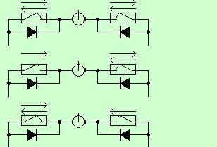
Limit switches are essential for servo motor operation with solar trackers. I made this diagram to help explain how they work.
Top. Normal operation between limit switches.Middle. The left limit switch has opened to stop movement to the left. To move to the right again the diode conducts current that allows movement to the right.Bottom. The right limit switch has opened to stop movement to the right. To move to the left again the diode conducts current that allows movement to the left.
Sellect a diode or rectifier rated at the maximum motor current plus some margine. Also the voltage should be at leat 100V and preferably 200V.
Needles to say, the limit switch must operate before the mechanical limits are reached. If the mechanical stop is reached before the switch the motor can draw quite high currents and can destroy the solar tracker.
Reprinted Url Of This Article:
http://www.seekic.com/circuit_diagram/Control_Circuit/How_Limit_Switches_Operate.html
Print this Page | Comments | Reading(3)

Article Categories
power supply circuit
Amplifier Circuit
Basic Circuit
LED and Light Circuit
Sensor Circuit
Signal Processing
Electrical Equipment Circuit
Control Circuit
Remote Control Circuit
A/D-D/A Converter Circuit
Audio Circuit
Measuring and Test Circuit
Communication Circuit
Computer-Related Circuit
555 Circuit
Automotive Circuit
Repairing Circuit
Code: