Basic Circuit
Basic Half Wave - DCC H-Bridge Circuit
Published:2013/6/21 2:41:00 Author:muriel | Keyword: Basic Half Wave , DCC H-Bridge Circuit | From:SeekIC

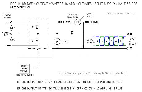
The next schematic shows a Half DCC H-Bridge circuit in a very basic form. The reversing switch has now been replaced by two transistors that are alternately switched ON and OFF.
Oscilloscopes A and B are not relevant to this circuit as the output of the bridge is actually referenced to the common of the power supply.
The waveform for the C oscilloscope above does apply to this circuit and illustrates why a 28 volt signal appears at the output while the instantaneous voltage does not exceed one half of the maximum supply voltage.
Reprinted Url Of This Article:
http://www.seekic.com/circuit_diagram/Basic_Circuit/Basic_Half_Wave___DCC_H_Bridge_Circuit.html
Print this Page | Comments | Reading(3)

Article Categories
power supply circuit
Amplifier Circuit
Basic Circuit
LED and Light Circuit
Sensor Circuit
Signal Processing
Electrical Equipment Circuit
Control Circuit
Remote Control Circuit
A/D-D/A Converter Circuit
Audio Circuit
Measuring and Test Circuit
Communication Circuit
Computer-Related Circuit
555 Circuit
Automotive Circuit
Repairing Circuit
Code: