Basic Circuit
Full Wave Rectification
Published:2013/6/21 2:42:00 Author:muriel | Keyword: Full Wave Rectification | From:SeekIC

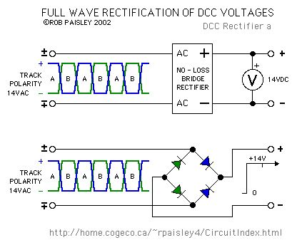
The next diagram shows the effect of rectifying a DCC voltage with a full wave bridge. The voltage at the output of the bridge is equal to the input minus the drop across the diodes.
The small tick in the output of the bridge occurs when the polarity of the H-Bridge reverses. The size of the ticks is largely determined by the efficiencies of the H-Bridge and rectifier bridge and in most cases can be ignored. This is why filter capacitors are not needed for decoders.Diodes used to rectify DCC should be Schottky or high speed silicon types. Diodes of the 1N4000 and 1N5400 series are not suitable for this application due to their slow turn-off times.
Reprinted Url Of This Article:
http://www.seekic.com/circuit_diagram/Basic_Circuit/Full_Wave_Rectification.html
Print this Page | Comments | Reading(3)

Article Categories
power supply circuit
Amplifier Circuit
Basic Circuit
LED and Light Circuit
Sensor Circuit
Signal Processing
Electrical Equipment Circuit
Control Circuit
Remote Control Circuit
A/D-D/A Converter Circuit
Audio Circuit
Measuring and Test Circuit
Communication Circuit
Computer-Related Circuit
555 Circuit
Automotive Circuit
Repairing Circuit
Code: