Basic Circuit
The 3 Amp Booster For My MiniDCC© System
Published:2013/6/21 2:45:00 Author:muriel | Keyword: 3 Amp, Booster, MiniDCC© System | From:SeekIC

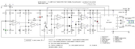
The following schematic is for the booster that was built for my MiniDCC® System. Designed around an LMD 18200 H-Bridge. The circuit includes signal failure detector and over current protection that will remove power to the tracks should either activate.
The signal detector will automatically clear itself but the over-current detector must be manually reset.
Reprinted Url Of This Article:
http://www.seekic.com/circuit_diagram/Basic_Circuit/The_3_Amp_Booster_For_My_MiniDCCcopy;_System.html
Print this Page | Comments | Reading(3)

Article Categories
power supply circuit
Amplifier Circuit
Basic Circuit
LED and Light Circuit
Sensor Circuit
Signal Processing
Electrical Equipment Circuit
Control Circuit
Remote Control Circuit
A/D-D/A Converter Circuit
Audio Circuit
Measuring and Test Circuit
Communication Circuit
Computer-Related Circuit
555 Circuit
Automotive Circuit
Repairing Circuit
Code: