
Circuit Diagram
Index 1789
TA1222N--the single chip integrated circuit of video small signal process
Published:2011/6/10 0:19:00 Author:qqtang | Keyword: single chip, integrated circuit, small signal
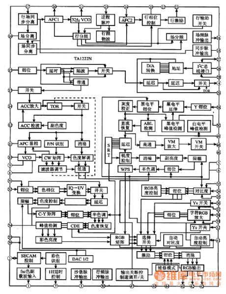
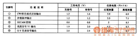
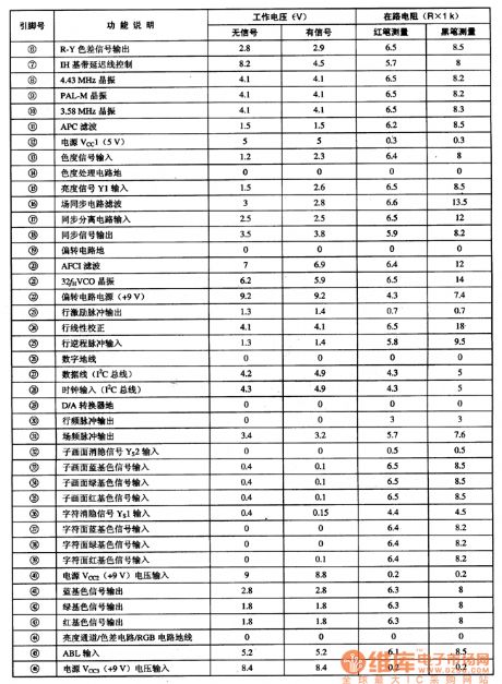
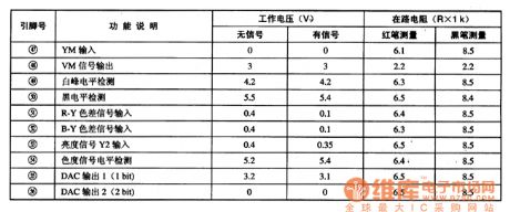
1.function featuresTA1222N is mainly used to fulfill functions of brightness signal process, chroma signal process and scanning deflection system small signal process, etc, the brightness signal process circuit includes high-quality image compensatory circuits, such as black LEV expanding circuit, DC LEV regain circuit, high brightness color circuit, delaying hole adjusting circuit and scanning speed signal generating circuit.2.pin functions and dataTA1222N is in 56-pin dual in-line package, whose pin functions are listed in Table 1.
(View)
View full Circuit Diagram | Comments | Reading(762)
TA1229--the SECAM decoding integrated circuit
Published:2011/6/10 0:07:00 Author:qqtang | Keyword: SECAM decoding, integrated circuit
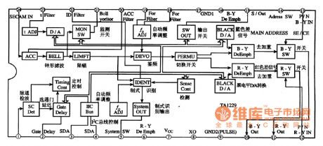
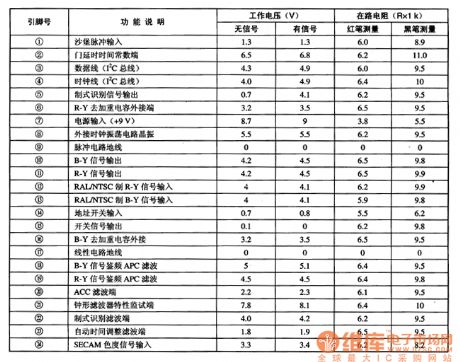
TA1229 is the SECAM decoding integrated circuit produced by Toshiba, which is widely used in local and imported large screen multi-system color TV, such as Changhong NC-6 core and so on.1.function featuresTA1229 consists of ACC amplifier, clock-shape filter, amplitude limiting amplifier, frequency discrimination circuit and aberration switch circuit and other auxiliary function circuits, etc.The internal circuit of auxiliary in shown in figure 1, and this IC circuit completes the SECAM system demodulation under the control the I2C general line.
(View)
View full Circuit Diagram | Comments | Reading(587)
TA7291P--the motor drive integrated circuit
Published:2011/6/9 22:43:00 Author:qqtang | Keyword: motor drive, integrated circuit
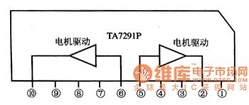
TA7291P is the dual-way motor drive integrated circuit produced by Toshiba, which is widely used in CD, VCD and other players.1.function featuresTA7291P contains two lines of same-function motor drive circuits, decoding drive control circuit, and other affiliated function circuits. The internal circuit of the IC is shown in figure 1.Figure 1. The internal circuit of TA7291P
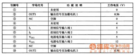
2.pin functions and dataTA7291P is in 10-pin single line package, whose pin functions and data are listed in table 1.
(View)
View full Circuit Diagram | Comments | Reading(1206)
TA7358P, TA7358AP and TA7358F--the integrated circuit of modulate high frequency
Published:2011/6/9 23:54:00 Author:qqtang | Keyword: integrated circuit, modulate high frequency
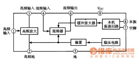
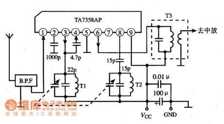
TA7358P/AP/F is the integrated circuit of modulate high frequency produced by Toshiba, which is widely used in all kinds of stereo radios, such as domestic stereo, car stereo and so on.1.function featuresTA7358P/AP/F contains FM high frequency amplifier, mixer, local oscillating circuit, bias and voltage steady circuit and buffer amplifier circuit, etc.The internal circuit of TA7358P/AP/F is shown in figure 1.Figure 1. The internal circuit of TA7358P/AP/F
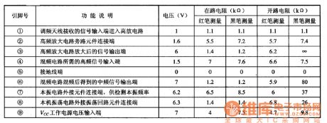
2.pin functions and dataTA7358P/AP/F is in three types of packages, we are using different suffixes to represent them.
(View)
View full Circuit Diagram | Comments | Reading(7925)
Typical Applied Circuit Diagram of LM386N Integrated Circuit
Published:2011/6/9 4:27:00 Author:Vicky | Keyword: LM386N Integrated Circuit,

Typical Applied CircuitThe typical applied circuit of power amplifier circuit which is composed of LM386 integrated circuit is shown in the following picture.
Hint: LM386N without suffix is a general type, the difference of different suffix only lies in the electrical parameter and package.
The limit parameter of LM386N一l: power supply voltage is 15V, and enable power dissipation is 0.66W
The limit parameter of LM386N一4: power supply voltage is 22V, and enable power dissipation is 1.25W
The limit parameter of LM386N一2 and LM386-3 is between the aboved two integrated
circuit. (View)
View full Circuit Diagram | Comments | Reading(1404)
Electromagnetic Oscillation Demonstrator Circuit Diagram
Published:2011/6/9 4:26:00 Author:Vicky | Keyword: Electromagnetic Oscillation Demonstrator,
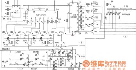
The picture is a circuit of electromagnetic oscillation demonstrator. It is displayed intuitively and visually in electromagnetic oscillation by the flow type pf luminous diode. The changing situation of galvanic current, magnetic field and electric field is also displayed in the procession of electromagnetic oscillation. Through coil current, it can display the change of circuit and magnetic field and the constitution of circuit, pulse drive circuit and work power supply.
(View)
View full Circuit Diagram | Comments | Reading(654)
The infrared lamp controller circuit
Published:2011/6/10 3:19:00 Author:qqtang | Keyword: infrared lamp controller
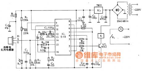
The infrared lamp controller is equipped with a heat releasing infrared sensor as the human body sensor, which can make the lamp controller fulfill functions of lighting with human being coming, cutting off when the people is away , it is especially suitable for hotels, departments, corridors of residential areas and homes.The circuit of the controller is in the figure, which mainly consists of the heat releasing infrared sensors, the infrared process integrated circuit S-01,the control circuit and the power, etc. The integrated circuit IC1 includes the amplifier, comparator, state controller and time delay unit,etc.
(View)
View full Circuit Diagram | Comments | Reading(1377)
NP83C266BDRNA--the single door microcomputer integrated circuit
Published:2011/6/9 21:31:00 Author:qqtang | Keyword: single door microcomputer, integrated circuit


1.function featuresNP83C266BDRNA consists of the CPU, clock oscillating circuit, reset control circuit, key pulse generating circuit, key order decoding circuit, remote order signal process circuit, I2C general control circuit, system control circuit, screen displayed letter generating and processing circuit and other control and additional functions circuits, etc.2.pin functions and data
(View)
View full Circuit Diagram | Comments | Reading(1751)
NJM2234L--the video amplifier and switch integrated circuit
Published:2011/6/9 21:40:00 Author:qqtang | Keyword: video amplifier, integrated circuit


NJM2234L is the video amplifier and switch integrated circuit produced by NJR, which is commonly used in large screen color TV as the video amplifier and multichannel shift switch.1.function featuresNJM2234L contains 3 the same-function video amplifier circuits, which is equal to the SP3T and other additional circuit. Its internal circuit is shown in the figure.
The internal circuit of NJM2234L2.pin functions and dataPin functions and data of NJM2234L
(View)
View full Circuit Diagram | Comments | Reading(1445)
The loudspeaker protection circuit
Published:2011/6/10 2:33:00 Author:qqtang | Keyword: protection circuit

In the figure is the loudspeaker protection circuit. The circuit is designed to have the left and right channels and they work separately.Elements selection: the LED can be the Φ3mm high brightness dual color LED. As the working current can be large or small. The parameters of R5 and R9 and be slightly adjusted. At the same time, LED and current limiting resistors R5 and R9 are connected with the two terminals of the relays (RE1 and RE2), so the inverting peak voltage can be impeded and VT2, VT3, VT5 and VT6 won't be broken down. It is better to choose low-leakage Tantalum capacitors for C4 and C9. The parameters of other elements are shown in Figure 1. (View)
View full Circuit Diagram | Comments | Reading(1275)
The electric bonsai circuit
Published:2011/6/10 2:48:00 Author:qqtang | Keyword: electric bonsai

Element selection: IC1~IC4 are two slices of dual D triggers CD4013; all the transistors VT are installed with 9013 PNP silicon triodes and so on, β>90. The types of LED are not limited, to achieve the flash effect, even the 5 LED in the same time may be of different colors. If the number of the LED is too small, it can be added, but the a little bigger transistors should be used, such as 8050 and DD01,etc. R10~R14 are the resistors of 470Ω. C1~C8 are the electrolytic capacitors of 1001μF/16V. S is a micro light touch power supply switch of CS-316. T is a micro power supply transformer of 220V/10V and 5W. (View)
View full Circuit Diagram | Comments | Reading(686)
The LED AC drive circuit
Published:2011/6/10 2:57:00 Author:qqtang | Keyword: AC drive circuit


See as the figure, the circuit can work normally under the condition whether the polarities of the voltage or power supply are right or not is unknown. As DC drive, when it is AC driven, the value of the limited resistance R is .In the formula, ERMS is the effective value of the AC current. (View)
View full Circuit Diagram | Comments | Reading(802)
The LED torch circuit
Published:2011/6/10 3:08:00 Author:qqtang | Keyword: LED torch

Generally, a problem of the small torch is that the life span of the battery is too short. According to the statistics, the power of a common torch is about 2W. See as the figure, the LED torch consumes power of 24mV/s, so 4 cells of No.5 can provide with more than 80 times of services(which means it can use for a month). Though the brightness of the torch is not high, but it is enough for ordinary torches. One of the cores of the torch is a 7555 time based circuit( the ordinary 555 can be used ). (View)
View full Circuit Diagram | Comments | Reading(1308)
Single chip microcomputer integrated circuit
Published:2011/6/8 1:45:00 Author:Christina | Keyword: Single chip, microcomputer, integrated circuit


The MNl52811TZX is designed as one kind of single chip microcomputer integrated circuit that is produced by the Panasonic corporation, and it can be used in the domestic and imported color TVs which use the Panasonic machine.
1.Features
The MN152811TZX integrated circuit is composed of the central processing unit (CPU), the clock oscillating circuit, the reset control circuit, the key instruction decoder circuit, the I2C bus control circuit, the remote control command signal processing circuit, the screen display circuit, the standby/boot control circuit, the mode selection circuit, the single-frequency control circuit and other control and auxiliary function circuits.
2.Pin functions and data
The MN152811TZX is in the 42-pin dual in-line package, the internal circuit block diagram and the signal flow are as shown in the figure, the pin-letter code and the data is as shown in the table.
The internal circuit block diagram and the signal flow of the MN152811TZX
The pin-letter code and the data of the MN152811TZX
(View)
View full Circuit Diagram | Comments | Reading(1268)
MN152810TZN single chip microcomputer integrated circuit
Published:2011/6/8 1:49:00 Author:Christina | Keyword: single chip, microcomputer, integrated circuit

The MN152810TZN is designed as one kind of single chip microcomputer integrated circuit that is produced by the Panasonic corporation, also it can be used in the large screen color TVs which are produced by the Panasonic corporation.
The MN152810TZN integrated circuit is in the 52-pin double-row type package, the pin functions and data is as shown in the table.
The pin functions and data of the MN152810TZN.
(View)
View full Circuit Diagram | Comments | Reading(617)
MN15281OTTD4 single chip microcomputer integrated circuit
Published:2011/6/8 1:58:00 Author:Christina | Keyword: single chip, microcomputer, integrated circuit


The MN15281OTTD4 is designed as one kind of single chip microcomputer integrated circuit that is produced by the Panasonic corporation, also it can be used in the large screen color TVs which are produced by the Panasonic corporation.
The MN15281OTTD4 integrated circuit is in the 52-pin double-row type package, the pin functions and data is as shown in the table.
The pin functions and data of the MN15281OTTD4.
(View)
View full Circuit Diagram | Comments | Reading(461)
Touch switch circuit composed of the photoelectric coupler
Published:2011/6/8 4:05:00 Author:Christina | Keyword: Touch switch, photoelectric coupler
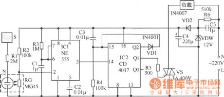
Working principle: The circuit which is composed of the capacitance C5, the regulator tube VDW, the diode VD2, the capacitance C4 and the resistance R6 can supply the 12V DC working voltage for the control part. When the hand touches the sheetmetal S, the neon tube N is ignited, the N and the photoconductive resistance RG form the photoelectric coupler, so at this time the resistance of RG becomes small, this makes the pin-2's electric potential of the integrated circuit 555 is lower than 1/3 of the power supply voltage, because of the NE555 was taken up into the monostable trigger, so the pin-3 of 555 sends out a positive pulse to the counting trigger port 14-pin of the integrated circuit, there is one count of the CD4017. (View)
View full Circuit Diagram | Comments | Reading(1520)
Outdoor antenna alarm circuit
Published:2011/6/8 4:05:00 Author:Christina | Keyword: Outdoor, antenna, alarm
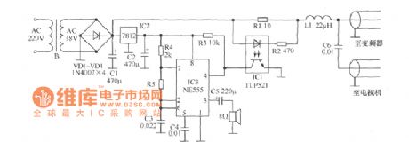
The outdoor antenna alarm circuit is as shown. The power supply of the microwave antenna is indoor, and the frequency converter is outdoor. They are connected with a 75 coaxial cable, this 75 coaxial cable is uses as the power cord and the signal line. In normal work, the current of 180mA~220mA gets through the electric cable, so we can form the alarm device by detecting this current and adding the simple alarm circuit. The current detection part is composed of the R1, R2, R3 and the photoelectric coupler IC1, the alarm device is composed of the NE555 and the peripheral components, the 7812 supplies the stable DC voltage for the 555. (View)
View full Circuit Diagram | Comments | Reading(1223)
Electric light touch switch circuit
Published:2011/6/8 3:37:00 Author:Christina | Keyword: Electric light, touch, switch circuit

The circuit principle is as shown, the photoelectric coupler is composed of the neon tubes N1 and N2, the photoresistor RG1. When the hand touches the sheetmetal S1, the N1 turns on and the resistance of RG1 becomes small, so the two-way thyristor VS1 conducts because it gets enough trigger current, so the bulb H gets power to light. At the same time, the 220V AC voltage of H makes the N2 to light, this light is shining on the RG1, so at this time, even you stop touching, VS1 remains in the conduction state, and the H still lights. In the figure, the photoelectric coupler is composed of the neon tube N3 and the photoresistor RG2. (View)
View full Circuit Diagram | Comments | Reading(2029)
Home Appliance Timing Blackouts Controller Circuit Composed of 555
Published:2011/6/2 3:35:00 Author:Joyce | Keyword: Home Appliance, Timing , Blackouts , Controller, 555
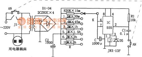
As shown in the figure is an electrical appliances timing blackouts control circuit.it consists of a step-down rectifier circuit, a timing circuit, and a relay control circuit etc among which the step-down rectifier circuit supplys power to the controller.
The timing circuit is a monostable delay circuit composed of IC (555) , R, C and some other components, and the timing time depends on the magnitude of charging and discharging time RC. When one stwiches on AN, 555 will start to set because the potential of feet ② is low level,and the high level output by feet③ will actuate relay J , so contacts J1-1 will be on to put the power through. At this time, timing starts and capacitor C will be charged through R. When the voltage of C is big enough to make the potential of feet⑥ of 555 higher than 2/3VDD, 555 will be reset,the low level output by feet③ will release relay J.so contacts J1-1 will cut off leading to appliance blackouts.The time for home appliance outages time can regulated by using K to choose different gears . (View)
View full Circuit Diagram | Comments | Reading(461)
| Pages:1789/2234 At 2017811782178317841785178617871788178917901791179217931794179517961797179817991800Under 20 |
Circuit Categories
power supply circuit
Amplifier Circuit
Basic Circuit
LED and Light Circuit
Sensor Circuit
Signal Processing
Electrical Equipment Circuit
Control Circuit
Remote Control Circuit
A/D-D/A Converter Circuit
Audio Circuit
Measuring and Test Circuit
Communication Circuit
Computer-Related Circuit
555 Circuit
Automotive Circuit
Repairing Circuit