
Circuit Diagram
Index 1785
AC Voltage Regulator Three
Published:2011/5/22 1:00:00 Author:Michel | Keyword: AC Voltage Regulator, Three

The AC voltage regulator introudced in the example has the functions of automatic voltage control and regulation.Its input voltage is from 120V to 260V,output voltage is 220V(11士10%)V and output power is from 300 to 1000W(It depends on transformer and relay contact terminal's current capacity).
Circuit's Work Principle
The AC voltage regulator circuit is composed of power supply circuit and voltage test circuit and it is showed as the picture 5-42.The power supply circuit consists of reduction voltage capacitor,C1 and C2,resistor,R1,commutation diode,VD1-VD4,filter capacitor,C3,voltage control diode,VS and transistor,transistor,V. (View)
View full Circuit Diagram | Comments | Reading(8049)
The circuit construction diagram of the double terminal output sensor
Published:2011/6/11 23:38:00 Author:qqtang | Keyword: circuit construction, output sensor
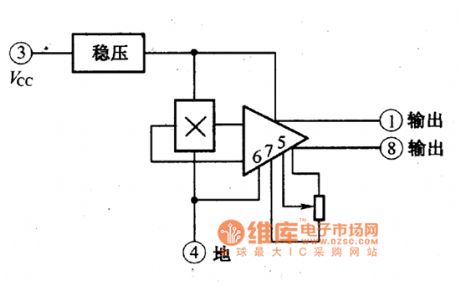
figure:The circuit construction of the double terminal output sensor (View)
View full Circuit Diagram | Comments | Reading(537)
The construction circuit of the single terminal output sensor
Published:2011/6/11 22:42:00 Author:qqtang | Keyword: construction circuit, single terminal output sensor
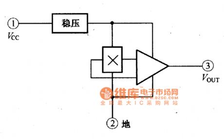
figure:The construction of the single terminal output sensor (View)
View full Circuit Diagram | Comments | Reading(518)
The dual steady circuit of photoelectric couplers and transistors
Published:2011/6/10 21:13:00 Author:qqtang | Keyword: dual steady circuit, photoelectric couplers

In the figure is dual steady circuit of photoelectric couplers and transistors. At the moment of power-on, the transistor VT is blocked, and the circuit outputs a high LEV. When the input pole is imposed with a positive pulse, the current in the VT collector electrode is rising, the photoelectric coupler and LED are glowing, the resistance between light dependent triodes are stepping down, as a result, the current on the basic pole of VT is increasing which forms a forward-backward feedback, and VT is saturated quickly, 1 becomes 0 . When it is input with a passive pulse, the current on VT collector electrode is reduced. (View)
View full Circuit Diagram | Comments | Reading(1082)
MT8803--the infrared remote controller integrated circuit
Published:2011/6/10 21:38:00 Author:qqtang | Keyword: infrared remote controller, integrated circuit


MT8803 is an infrared remote controller integrated circuit, which often forms the fan remote control system with the remote signal receiver circuit MR8181 and the fan single chip integrated circuit MH8822, such as the Great Wall fan and the like. MT8803 is in 16-pin dual line package, whose typical application circuit is shown in the figure, and its pin functions and data are listed in the figure.
The typical application circuit of MT8803 The pin functions and data of MT8803
(View)
View full Circuit Diagram | Comments | Reading(772)
MSP3410B--the multi-system sound process single chip integrated circuit
Published:2011/6/10 21:47:00 Author:qqtang | Keyword: multi-system sound process, single chip


1.function featuresMSP3410B contains the A/D converting circuit, D/A converting circuit, I2C general and I2C general connector circuit, S general connector circuit, sound demodulation circuit, NICAM decoding circuit, audio output shifting circuit and other additional function circuit. The internal circuit of MSP3410B is shown in the figure.
The internal circuit of MSP3410B2.pin functions and dataMSP3410B is in 68-pin square package, whose pin functions and data are listed in the table.The pin functions and data of MSP3410B
(View)
View full Circuit Diagram | Comments | Reading(669)
MR8181--the integrated circuit of the infrared remote signal receiver
Published:2011/6/10 21:57:00 Author:qqtang | Keyword: integrated circuit, infrared remote signal receiver

MR8181 is an integrated circuit of the infrared remote signal receiver, which is often used with the remote emitter integrated circuit MT8803, fan single chip microcomputer integrated circuit MH8822, and they form the fan remote control system, such as the Great Wall fan and the like.1.pin functions and dataMR8181 is in 8-pin single line package, whose pin functions and data are listed in table 2.
The pin functions and data of MR8181
2.the typical application circuitThe typical application circuit of the remote signal receiver, which consists of MR8181, is shown in the figure of MH8822. (View)
View full Circuit Diagram | Comments | Reading(556)
The LT current sensor outline circuit
Published:2011/6/10 22:01:00 Author:qqtang | Keyword: current sensor, outline
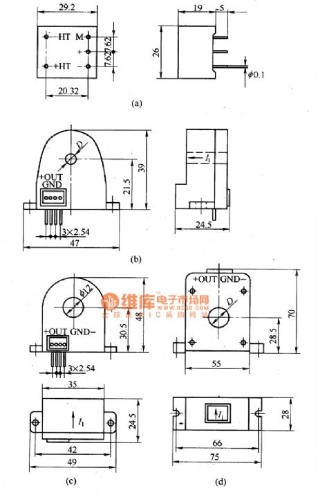
figure:The LT current sensor outline circuit (View)
View full Circuit Diagram | Comments | Reading(585)
Switch D. C. Regulated Power Supply Three
Published:2011/6/3 5:00:00 Author:Michel | Keyword: Switch, D. C., Regulated Power Supply, Three


The switch D. C. regulated power supply circuit introduced in the example uses TWH8778 electronic switching IC and it has high work's efficiency,its circuit is simple which is easy to manufature.The output voltage and current of the power supply circuit are +12V and 1A respectively.
Work's Principle of the CircuitThe switch D. C. regulated power supply circuit is composed of input converting circuit,switch output circuit and automatical voltage regulator circuit and it is showed as the picture 5-39.
The input converting circuit consists of mains switch S,mains transformer T,commutation diode VD1-VD4 and filter capacitor C1.The switch output circuit is composed of electronic switching intergrated circuit,IC,resistor R1,R2, diode,VD5,induction coil,L and capacitor C2,C3. (View)
View full Circuit Diagram | Comments | Reading(1097)
MN1874876TSH--the single door microcomputer integrated circuit
Published:2011/6/10 22:22:00 Author:qqtang | Keyword: single door microcomputer, integrated circuit


1.function featuresMN1874876TSH consists of the clock oscillating circuit, CPU, reset circuit, key decoding circuit, screen display circuit, I2C general circuit and other affiliated function circuits.2.pin functions and dataMN1874876TSH is in 64-pin dual in-line package, whose internal circuit, pin functions and signal flow are shown in the figure, and the pin letter codes and data are listed in the table.
The internal circuit, pin functions and signal flow of MN1874876TSH
(View)
View full Circuit Diagram | Comments | Reading(487)
The working principle circuit of magnetic compensatory current sensors
Published:2011/6/10 22:12:00 Author:qqtang | Keyword: working principle, magnetic compensatory current
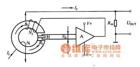
The introduction of the working principleIn the figure is the working principle circuit of magnetic compensatory current sensors. Accroding to the Ampere's law, the current under test will generate a field B2, and the field is compensated by the field generated by I2M2 and kept balanced, i.e I1M1=I2M2, so I2=I1M1/N2. When N1/N2 spot is determined, I2 is proportional to I1, and it is switched into a voltage signal by Rm and output. The Hall elements is testing the zero flux all the time.
Figure:The the working principle circuit of magnetic compensatory current sensors (View)
View full Circuit Diagram | Comments | Reading(811)
The photoelectric counting circuit
Published:2011/6/10 5:12:00 Author:qqtang | Keyword: photoelectric, counting circuit
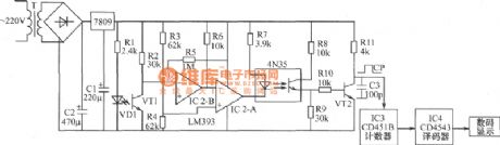
See as the figure, when thelight dependenttriode VT1 receives the infrared rays from the diode, VT1 is conducting, the inverting input terminal 6-pin of the comparator IC2-8 is in a low LEV, 7-pin outputs a high LEV which is added to the inverting terminal of the comparator IC2-A, which makes the 1-pin output a low LEV, so the lighting pipe in photocoupler 4N35 is glowing and the corresponding light dependent pipe is conducting, the triode pipe VT2 is conducting, VT2 pole outputs a low LEV. The something crosses between LED VD1 and the receiving pipe VT1, the infrared is blocked. (View)
View full Circuit Diagram | Comments | Reading(1186)
The typical application circuit of photoelectric couplers in audio amplifier circuits
Published:2011/6/10 20:09:00 Author:qqtang | Keyword: typical application circuit, photoelectric couplers, audio amplifier circuits
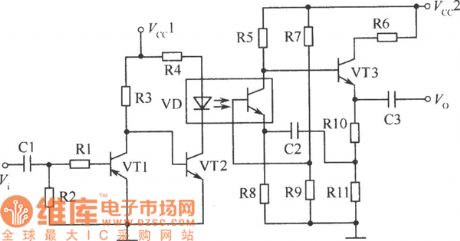
By fixing photoelectric couplers in audio amplifier circuits, not only the signals can be separated and the noise between stages can be impeded, but the audio signals can be amplified. In the circuit, photoelectric coupler can replace the audio transformer and overcome signal consumption and distortion, etc, it can also reduce the magnetic interference and the like. In the figure, VT1 and VT2 form a two-stage direct coupling amplifier circuit. The sensor or source signals are sent into the preamplifier consisting of VT1 and VT2 with the help of C1 and R1. (View)
View full Circuit Diagram | Comments | Reading(935)
AC Voltage Regulator Two
Published:2011/5/22 0:57:00 Author:Michel | Keyword: AC Voltage Regulator, Two

The AC voltage regulator introudced in the example can control and regulate voltage automatically,cut off when it is idle load and voltage is over to save engery and protect the regulator.The regulator's input voltage range is from 65V to 250V,output voltage range is 195V to 230V and output power is 500W.
Circuit's Work Principle
The AC voltage regulator circuit is composed of power supply voltage control,voltage test,control circuit and time delay circuit and it is showed as the picture 5-41.The power supply voltage control consists of mains transformer,T,rectifier bridge,UR,filter capacitor,C6 and C7,three-terminal voltage control IC,IC2 and power indication LED,VL3 and current-limiting resistor,R14.
(View)
View full Circuit Diagram | Comments | Reading(4487)
The gate circuit of photoelectric couplers
Published:2011/6/10 20:14:00 Author:qqtang | Keyword: gate circuit, photoelectric couplers

The gate circuit of photoelectric couplers(a) AND gate; (b)and NAND gate; (c)OR gate; (d) NOR gate (View)
View full Circuit Diagram | Comments | Reading(1040)
The computer connector LEV coupling circuit of photoelectric couplers
Published:2011/6/10 20:23:00 Author:qqtang | Keyword: computer connecto, LEV coupling circuit

In computer systems, all kinds of semi-conductor logic circuits are connected with consciousness, and the different logic circuits requires different power supply voltages. Therefore, different logic circuits can be inter-connected, which is done after the LEV shifting, and it can be fulfilled by photoelectric couplers. For example, TTL integrated circuit characterizes fast speed and low price, etc, which is suitable for the computing part of the computer and the HTL circuit with high anti-disturbance, and it can normally work in the environment of high noise voltages. (View)
View full Circuit Diagram | Comments | Reading(891)
The eyesight feature circuit of the heat releasing electric infrared sensor
Published:2011/6/11 23:41:00 Author:qqtang | Keyword: eyesight feature, infrared sensor
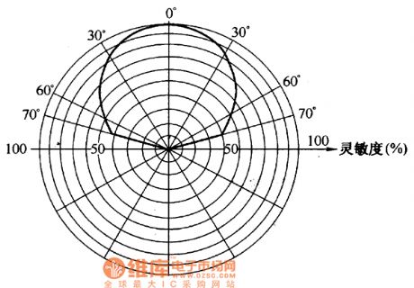
The eyesight feature of the heat releasing electric infrared sensor is shown in the figure.
figure:The eyesight feature of the heat releasing electric infrared sensor is shown in the figure. (View)
View full Circuit Diagram | Comments | Reading(541)
The switch circuit with two normally open contacts and closed contacts
Published:2011/6/10 20:33:00 Author:qqtang | Keyword: switch circuit, normally open contacts, closed contacts
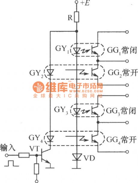
In the figure is the switch circuit with two normally open contacts and closed contacts, when the input signal is a low LEV 0 , the transistor TV is blocked, the LED GY2 and GY4 in the photoelectric couplers have no currents, and the light dependent triodes GG2 and GG4 are blocked, which is equal to the switch cutting off, we call them the normally open contact; however, when there are currents in GY1 and GY3, which makes GG1 and GG3 conducting, that is equal to switch closing, we call them the normally closed contact. When the input signals are high LEV 1 , the transistor VT is conducting. (View)
View full Circuit Diagram | Comments | Reading(964)
The spectral character circuit of light filter
Published:2011/6/10 21:26:00 Author:qqtang | Keyword: spectral character

The sensor consists of the shell, light filter, heat electric element PZT, FET pipe, resistor and diode,etc. The light filter is installed at the window, which forms a infrared window. The light filter is a multi-film interference filter of 6μm, this filter has a high reflection ratio on sunlight and daylight lamp light that the short wave is under 5μm, but it has a high penetration on the infrared ray source(10μm) which is emitted by human bodies and higher than 6μm, the spectral characters are as shown in figure 26-62.
(View)
View full Circuit Diagram | Comments | Reading(531)
The switch circuit with functions of self-lock (auto keeping) (1)
Published:2011/6/10 20:43:00 Author:qqtang | Keyword: switch circuit, self-lock
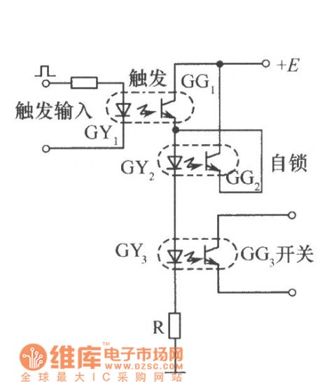
In the figure is a switch circuit with functions of self-lock (auto keeping). The 3 photoelectric couplers fulfill functions of trigger, self-lock and switch. When there are trigger signals on GYI, GG1 is conducting, GY2 and GY3 are glowing because of the currents in them, and GG2 and OG3 are conducting. When the trigger signals disappear, GY1 is put out and GG1 is blocked, but GG2 is conducting now, the currents of GY2 and GY3 are provided by GG2, GG3 remains in the conducting state, which is equal to switch going on conducting and the circuit won't recover until the power supply voltage E is gone. (View)
View full Circuit Diagram | Comments | Reading(1036)
| Pages:1785/2234 At 2017811782178317841785178617871788178917901791179217931794179517961797179817991800Under 20 |
Circuit Categories
power supply circuit
Amplifier Circuit
Basic Circuit
LED and Light Circuit
Sensor Circuit
Signal Processing
Electrical Equipment Circuit
Control Circuit
Remote Control Circuit
A/D-D/A Converter Circuit
Audio Circuit
Measuring and Test Circuit
Communication Circuit
Computer-Related Circuit
555 Circuit
Automotive Circuit
Repairing Circuit