
Circuit Diagram
Index 1796
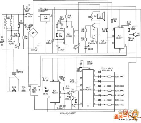
7W electronic repellent circuit
Published:2011/6/8 7:41:00 Author:chopper | Keyword: 7W, electronic repellent

View full Circuit Diagram | Comments | Reading(793)
Typicall Applied Circuit Diagram of LM8560 Integrated Circuit
Published:2011/6/9 3:42:00 Author:Vicky | Keyword: LM8560 Integrated Circuit, LM8560

Picture: Typical Applied Circuit of LM8560 Integrated Circuit (View)
View full Circuit Diagram | Comments | Reading(7147)
15W electronic repellent circuit
Published:2011/6/8 7:40:00 Author:chopper | Keyword: 15W, electronic repellent
View full Circuit Diagram | Comments | Reading(717)
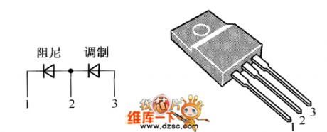
crystal diode DMV1500HDFD internal circuit
Published:2011/6/8 7:39:00 Author:chopper | Keyword: crystal diode, internal
View full Circuit Diagram | Comments | Reading(638)
Mouse expeller with electronic cat circuit
Published:2011/6/8 7:38:00 Author:chopper | Keyword: Mouse expeller, electronic cat

View full Circuit Diagram | Comments | Reading(998)
30 kHs bandwidth isolation circuit
Published:2011/6/8 7:36:00 Author:chopper | Keyword: 30 kHs bandwidth, isolation

This circuit uses A-8402V/F convertor whose linearity is ±0.05%,the greatest inversion frequency can reach 500KHZ,and the convertor can drive the LED of optoelectronic isolator.Another A-8402V/F module is used to convert the output of optoelectronic isolator into DC voltage accordingly.The power source is 12V ,and 5~18V is ok. (View)
View full Circuit Diagram | Comments | Reading(589)
The reaper warehouse full reminder circuit (2)
Published:2011/6/5 5:59:00 Author:qqtang | Keyword: reaper warehouse, full reminder
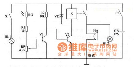
Working principle
In the circuit, the photoelectric detection amplifier consists of indicator HL1, lamp switch S1, LDR resistor RG, resistor R1 and R2, potentiometer RP and NPN v1; the acousto-optic siren circuit consists of NPN V2, relay K, diode VD, indicator HL2 and buzzer HA. When using it, fix the reminder circuit in a small control box, RG and HL on the front-end plate of the control box, S1, S2 and HA on the rear board of the control box, locate HL2 in a place which the working man can easily see.
(View)
View full Circuit Diagram | Comments | Reading(628)
Digital Photoelectric Counter Circuit Diagram
Published:2011/6/9 3:52:00 Author:Vicky | Keyword: Digital Photoelectric Counter,

Some digital electronic counters adopt mechanical trigger, and some adopt non-contact trigger of electronic sensor; photoelectric sensor, belonging to the latter, is a non-contact electronic sensor. Photoelectric electronic counter made of photoelectric sensor is shown in the following picture. When used to counting the products in producing streamlines in the factory, this kind of counter has irreplaceable strong point. In this case, the photoelectric triggering electronic counter has only two digits, but it can expand to four digits and even more via cascading. (View)
View full Circuit Diagram | Comments | Reading(1540)
Comparative Capacitance Gradienter Circuit Diagram
Published:2011/6/9 3:58:00 Author:Vicky | Keyword: Comparative Capacitance Gradienter,

Comparative Capacitance Gradienter is used to make comparison between the tested capacitance and standard capacitance and test whether the capacity of the tested capacitance is more or less than the standard value. Comparative Capacitance Gradienter can be used to test whether some product meets the design standard or not quickly, so as to make sure that the quality of products meets the requirement. The circuit composition is as shown in the picture. (View)
View full Circuit Diagram | Comments | Reading(957)
Multifunctional Motor Protector (2)
Published:2011/5/25 6:18:00 Author:Sue | Keyword: Multifunctional, Motor, Protector
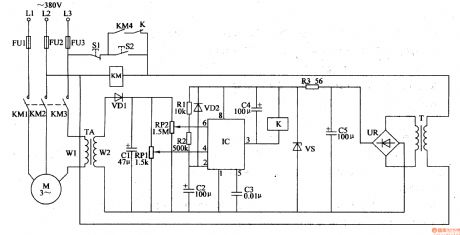
When the motor is working well, TA's induced voltage is low, IC's 6 pin's voltage is lower than 2Vcc/3, 3 pin outputs low level. K is not connected.
When L2 or L1 lacks phase, L3's phase current will be larger. TA's induced voltage will be lager. IC's 6 pin's voltage is higher than 2Vcc/3. 3 pin will have low level. KM is released and M stops working.
When the motor is overload, L1-L3 will have larger current. When the current reaches 1.2 times rated current, IC's 6 pin will have a voltage higher than 2Vcc/3. M will stop working. (View)
View full Circuit Diagram | Comments | Reading(552)
Frequency Calibrator Circuit Diagram
Published:2011/6/9 3:59:00 Author:Vicky | Keyword: Frequency Calibrator,

A Frequency Calibrator can be made by utilizing frequency lock, feature of PLL (Phase Locking Loop), whose circuit composition isas shown in thepicture. The circuit of Frequency Calibrator is composed of the amplifier and shaping circuit of input signal, generator circuit of standard frequency signal, comparative detection circuit of frequency signal, and indication circuit of test results. (View)
View full Circuit Diagram | Comments | Reading(1103)
Temperature-Frequency Conversion Circuit Diagram
Published:2011/6/9 3:58:00 Author:Vicky | Keyword: Temperature-Frequency Conversion Circuit, CD4046

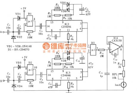
Temperature-Frequency Conversion Circuit is an indispensable part of radio telemetry temperature circuit. The principle of Temperature-Frequency Conversion Circuit is to convert the change of temperature to the change of voltage and use changing voltage to control the change of the oscillating frequency of oscillatory circuit. The changing frequency then is sent by wireless after signal encoding. After the sent signal is received by receiving set, the changing frequency would restore as value of temperature and display via the screen after demodulating, converting and decoding. The diagram of Temperature-Frequency Conversion Circuit composed of CD4046 is as shown in the picture. (View)
View full Circuit Diagram | Comments | Reading(726)
The electric adjuster circuit of temperature control fans
Published:2011/6/4 2:38:00 Author:qqtang | Keyword: electric adjuster, temperature control
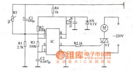
The working principle of the circuit This adjuster circuit consists of voltage-steady circuit, multi-resonate oscillator and control executing circuit, see as Figure 1.
In the circuit, the voltage-steady circuit consists of resistor R4, filtering capacitor C3 and voltage-steady diode VS; the oscillator consists of time-based integrated circuit IC, resistor R1-R3, capacitor C1 and C2 and thermistor RT; the control executing circuit consists of resistor R5, thyristor VT and fan motor M. When the power is on, the multi-oscillator is starting to work. (View)
View full Circuit Diagram | Comments | Reading(549)
Multifunctional Motor Protector (3)
Published:2011/5/25 6:23:00 Author:Sue | Keyword: Multifunctional, Motor, Protector
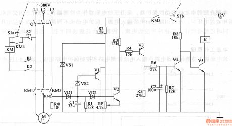
When S1 is pushed, V5 is connected and K is connected. K1 K2 are connected and M begins to work. The current detection control circuit begins to work.
When the motor works well, RO's voltage is low, V1-V4 are disconnected and V5 is connected.
When the motor is overloaded or the voltage is low, RO's voltage will be higher. V2-V4 will be connected and V5 is disconnected. K is released and K1 K2 are disconnected. M stops working. (View)
View full Circuit Diagram | Comments | Reading(609)
Pulse Demodulator Circuit Diagram
Published:2011/6/9 3:58:00 Author:Vicky | Keyword: Pulse Demodulator, CD4069

As is shown in the picture, the Pulse Demodulator is composed by CMOS Hex Inverter. This circuit can be used to process envelop detection on Amplitude Pulse. (View)
View full Circuit Diagram | Comments | Reading(1619)
The radiation tester circuit
Published:2011/6/6 2:02:00 Author:Seven | Keyword: radiation tester
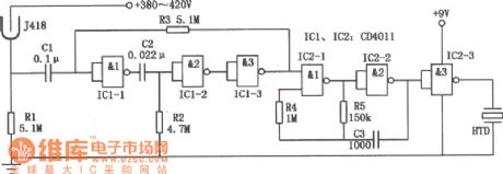
In the figure is the radiation tester circuit,which consists of the radiation testing sensor and the NAND integrated circuit CD4011. It can be used to detect the α,γ,βand X rays, and the sensitivity is high. When a few radioactive rays are detected, the tester will make intermittent noises; and when the dose of the rays is big, it will make continuous warning noises.
(View)
View full Circuit Diagram | Comments | Reading(729)
The illuminance tester circuit
Published:2011/6/6 1:32:00 Author:Seven | Keyword: illuminance tester
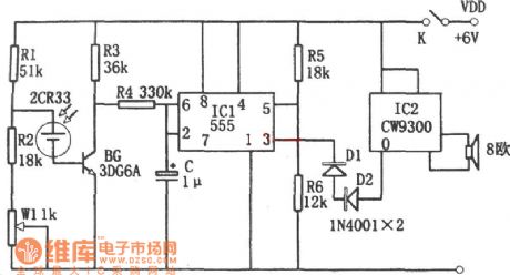
In the figure is an illuminance tester circuit. The tester consists of the photoelectric sensor, single steady trigger, stereo circuit, etc, of which the photoelectric sensor is powered by battery 2CR33.
(View)
View full Circuit Diagram | Comments | Reading(638)
Internal Circuit Block Diagram of LNO99 Integrated Circuit
Published:2011/6/9 4:00:00 Author:Vicky | Keyword: LNO99 Integrated Circuit,

Function and Characteristic
By different choice of the internal storage system, the LV099 integrated circuit can provide 8 rhythms, auto-chords, bass control and beating points of 16 timing series of 4 Percussion. When used with M208 integrated circuit, it can automatically decompose the various storage beating points. The internal circuit block diagram is shown in the picture. (View)
View full Circuit Diagram | Comments | Reading(927)
Electronic Gradienter Circuit Diagram
Published:2011/6/9 3:57:00 Author:Vicky | Keyword: Electronic Gradienter,

Ordinary gradienter confirms whether the plane of tested object reached the level by observing whether the air bubble in the middle of spirit level is in the centre. Under the dim environment, naked eyes cannot see object clearly and thus is hard to justify accurately. Electronic gradienter indicates whether the plane of object reaches the level by acoustooptical change. Therefore it can be used to measure under environment of any luminance, which is very convenient. Thepicture is the circuit diagram of electronic gradienter. (View)
View full Circuit Diagram | Comments | Reading(721)
The digital capacitor tester
Published:2011/6/6 1:26:00 Author:Seven | Keyword: capacitor tester

In the figure is the digital capacitor tester. The tester consists of the time-based pulse generator, single steady trigger, addition counter, decoder, driver and LED digital pipe, etc.
(View)
View full Circuit Diagram | Comments | Reading(1023)
| Pages:1796/2234 At 2017811782178317841785178617871788178917901791179217931794179517961797179817991800Under 20 |
Circuit Categories
power supply circuit
Amplifier Circuit
Basic Circuit
LED and Light Circuit
Sensor Circuit
Signal Processing
Electrical Equipment Circuit
Control Circuit
Remote Control Circuit
A/D-D/A Converter Circuit
Audio Circuit
Measuring and Test Circuit
Communication Circuit
Computer-Related Circuit
555 Circuit
Automotive Circuit
Repairing Circuit