Signal Processing
The electric adjuster circuit of temperature control fans
Published:2011/6/4 2:38:00 Author:qqtang | Keyword: electric adjuster, temperature control | From:SeekIC

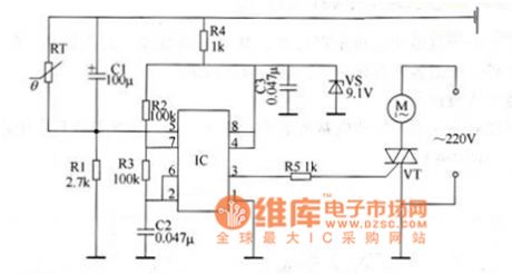
The working principle of the circuit This adjuster circuit consists of voltage-steady circuit, multi-resonate oscillator and control executing circuit, see as Figure 1.
In the circuit, the voltage-steady circuit consists of resistor R4, filtering capacitor C3 and voltage-steady diode VS; the oscillator consists of time-based integrated circuit IC, resistor R1-R3, capacitor C1 and C2 and thermistor RT; the control executing circuit consists of resistor R5, thyristor VT and fan motor M. When the power is on, the multi-oscillator is starting to work.
Reprinted Url Of This Article:
http://www.seekic.com/circuit_diagram/Signal_Processing/The_electric_adjuster_circuit_of_temperature_control_fans.html
Print this Page | Comments | Reading(3)

Article Categories
power supply circuit
Amplifier Circuit
Basic Circuit
LED and Light Circuit
Sensor Circuit
Signal Processing
Electrical Equipment Circuit
Control Circuit
Remote Control Circuit
A/D-D/A Converter Circuit
Audio Circuit
Measuring and Test Circuit
Communication Circuit
Computer-Related Circuit
555 Circuit
Automotive Circuit
Repairing Circuit
Code: