
Circuit Diagram
Index 1799
Scintillation Caution Light (8)
Published:2011/6/3 5:56:00 Author:Sue | Keyword: Scintillation, Caution, Light

In the daytime, soler energy battery GB1 will charge GB2 through VD1. The other circuit will provide D1 and D4 with high level through VD2, and D1's andD4's output terminals will have low level. V1 and V2 are disconnected and VL1-VL4 are not illuminated.
At night, VD1 and VD2 are disconnected. GB2 will provide the circuit with working voltage. When the multivibrator begins to work, D3's output terminal will output low frequency oscillator signals which will illuminated VL1-VL4. When the signal has high level, VD3 is connected and D1's andD4's input terminals have high level and their output terminals have low level. V1 and V2 are disconnected. VL1-VL4 are not illuminated. When the signal has low level, VD3 is disconnected. V1 V2 are connected and VL1-VL4 are illuminated. (View)
View full Circuit Diagram | Comments | Reading(416)
The AC voltage regulation circuit with stabilization sectors
Published:2011/6/2 6:38:00 Author:Seven | Keyword: voltage regulation, stabilization sectors

View full Circuit Diagram | Comments | Reading(708)
The auto power limiting circuit of PNP
Published:2011/6/2 3:16:00 Author:Seven | Keyword: power limiting circuit, PNP

View full Circuit Diagram | Comments | Reading(599)
The automatic switching circuit of the dual-way 3-phase power supply
Published:2011/6/2 3:11:00 Author:Seven | Keyword: automatic switching circuit, power supply

View full Circuit Diagram | Comments | Reading(1646)
The 875p computer main board circuit (092)
Published:2011/6/5 1:40:00 Author:Seven | Keyword: main board

View full Circuit Diagram | Comments | Reading(428)
The 875p computer main board circuit (095)
Published:2011/6/5 1:46:00 Author:Seven | Keyword: main board

View full Circuit Diagram | Comments | Reading(394)
The 875p computer main board circuit (096)
Published:2011/6/5 1:48:00 Author:Seven | Keyword: main board

View full Circuit Diagram | Comments | Reading(382)
The trigger circuit of crystallizer pipes
Published:2011/6/2 2:53:00 Author:Seven | Keyword: trigger circuit, crystallizer pipe

View full Circuit Diagram | Comments | Reading(360)
The 875p computer main board circuit (098)
Published:2011/6/5 1:38:00 Author:Seven | Keyword: main board

View full Circuit Diagram | Comments | Reading(410)
The 875p computer main board circuit (093)
Published:2011/6/5 1:43:00 Author:Seven | Keyword: main board

View full Circuit Diagram | Comments | Reading(409)
The 875p computer main board circuit (102)
Published:2011/6/5 1:22:00 Author:Seven | Keyword: main board

View full Circuit Diagram | Comments | Reading(382)
Scintillation Caution Light (7)
Published:2011/6/3 5:57:00 Author:Sue | Keyword: Scintillation, Caution, Light

The 220V alternating current voltage will provide the oscillator with +5V working voltage after reduction, stablization, rectification and filtration.
In the daytime, RG has a low resistancevalue because of the light. C3 has a low level and the oscillator doesn't work. VLC and VT are disconnected. HL is not illuminated.
At night, RG has a high resistance value because of the lack of light. The oscillator begins to work and VLC and VT are connected intermittently. HL begins to twinkle. (View)
View full Circuit Diagram | Comments | Reading(526)
The 875p computer main board circuit (103)
Published:2011/6/5 1:30:00 Author:Seven | Keyword: main board

View full Circuit Diagram | Comments | Reading(381)
TC9083N and TC9083F--the integrated circuit of single chip PIP control
Published:2011/6/6 23:27:00 Author:qqtang | Keyword: integrated circuit, single chip, PIP control
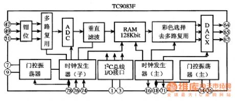
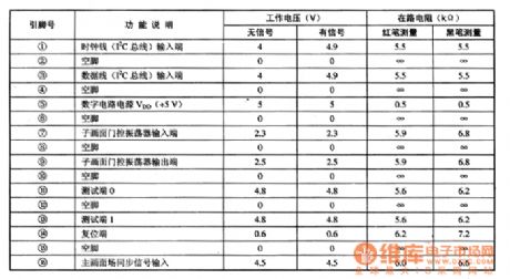
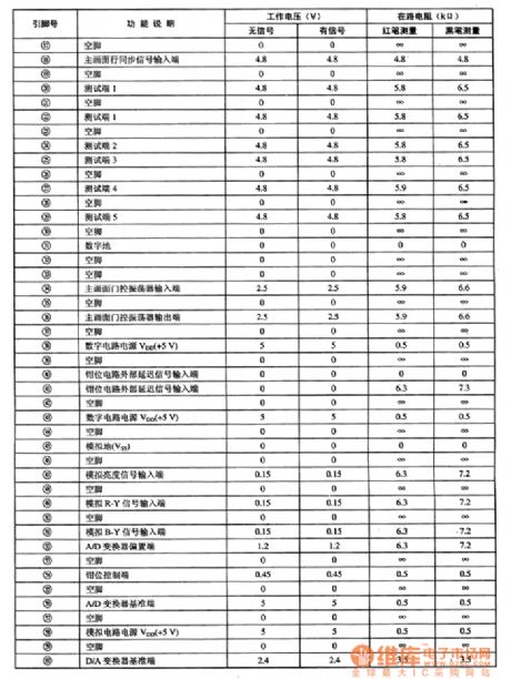
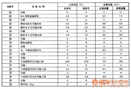
Both TC9083N and TC9083F are integrated circuitsof single chip PIP control produced by Toshiba, which is widely used in local and imported large screen PIP color TV, such as Changhong NC-6 cores, KONKA T2988/3488/3888 color TV and so on .1.function featuresThe internal circuits of TC9083N and TC9083F are almost the same but the package. Take TC9083F as an example, it contains sub-circuits, such as a line of 6 bit A/D converter, 3 lines of 12k bit dynamic storage, clock generator, PIP controller and so on, which is suitable for many kinds of signal PIP processing.
(View)
View full Circuit Diagram | Comments | Reading(504)
The 875p computer main board circuit (097)
Published:2011/6/5 1:49:00 Author:Seven | Keyword: main board

View full Circuit Diagram | Comments | Reading(380)
The 875p computer main board circuit (099)
Published:2011/6/5 1:29:00 Author:Seven | Keyword: main board

View full Circuit Diagram | Comments | Reading(385)
Scintillation Caution Light (6)
Published:2011/6/3 5:45:00 Author:Sue | Keyword: Scintillation, Caution, Light

In the daytime, RG has a lowresistance valuebecause of the light. D1's b terminal has a low level and the oscillator doesn't work. D1 outputs high level. D2-D4 output low level. HL1-HLn are not illuminated.
At night, RG has a high resistance value. D1's b terminal has high level and the oscillator begins to work. VLC and VT are connected from time to time, which will make HL1-HLn twinkle. When the oscillator outputs negative pulse signal, D2-D4 output high level and VLC's LED is illuminated. HL1-HLn are illuminated. When the signal is positive, D2-D4 output low level, VLC and VT are disconnected. HL1-HLn are not illuminated. (View)
View full Circuit Diagram | Comments | Reading(436)
The circuit of fans with display functions
Published:2011/6/6 23:09:00 Author:qqtang | Keyword: fans, display

The principle circuit is shown in the following figure, it cuts off the X spots of the speed phase lines in turn, and links to the step-down resistors of R1~R3. When the wind speed switch K is on some gear, the conducting current provides the LED digital pipe with power by VD2~VD7, and now the gear number can be displayed. When the gear switch K is shifting, the coil circuit is cut off.
(View)
View full Circuit Diagram | Comments | Reading(487)
The 875p computer main board circuit (100)
Published:2011/6/5 1:27:00 Author:Seven | Keyword: main board

View full Circuit Diagram | Comments | Reading(373)
The 875p computer main board circuit (101)
Published:2011/6/5 1:25:00 Author:Seven | Keyword: main board

View full Circuit Diagram | Comments | Reading(379)
| Pages:1799/2234 At 2017811782178317841785178617871788178917901791179217931794179517961797179817991800Under 20 |
Circuit Categories
power supply circuit
Amplifier Circuit
Basic Circuit
LED and Light Circuit
Sensor Circuit
Signal Processing
Electrical Equipment Circuit
Control Circuit
Remote Control Circuit
A/D-D/A Converter Circuit
Audio Circuit
Measuring and Test Circuit
Communication Circuit
Computer-Related Circuit
555 Circuit
Automotive Circuit
Repairing Circuit