
Circuit Diagram
Index 1797
The controllable silicon fast tester circuit
Published:2011/6/6 1:20:00 Author:Seven | Keyword: controllable silicon, fast tester
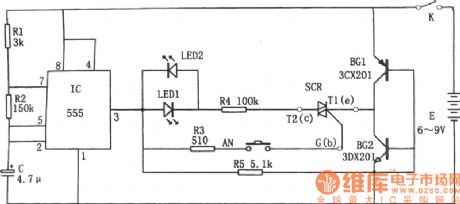
In the figure is the controllable silicon fast tester circuit. The tester consists of pulse signal generator, close-loop conducting circuit, LED and controllable silicon SCR, etc.
The pulse signal generator is a multi-resonate oscillator which consists of the time-based circuit 555, R1, R2 and C, etc, the oscillating frequency is f=1.44/(R1+2R2)C. The oscillating frequency of the parameter in the figure is about 1Hz. As R1<<R2, so the charging time of C is t(charging)=0.693(R1+R2)C, and it is close to the discharging time which is 0.693R2C, so the duty cycle of the output pulse is close to 1:1. (View)
View full Circuit Diagram | Comments | Reading(819)
Typical Applied Circuit Diagram of LN099 Integrated Circuit
Published:2011/6/9 3:59:00 Author:Vicky | Keyword: LN099 Integrated Circuit

Typical Applied Circuit
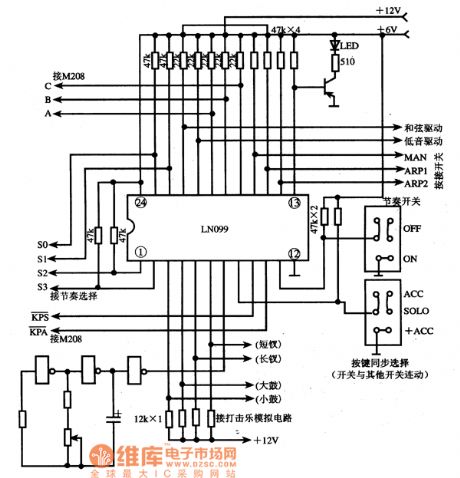
Typical applied circuit diagram of rhythmer section, which is composed of LN099 integrated circuit, is shown in the aboved picture. (View)
View full Circuit Diagram | Comments | Reading(790)
The electric speed regulator circuit of ceiling fans
Published:2011/6/4 3:02:00 Author:qqtang | Keyword: speed regulator, ceiling fans

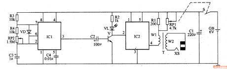
The regulator circuit consists of the power supply circuit, non-steady multi-resonate oscillator and control execute circuit, see as figure 1.
In the circuit, the power supply circuit consists of fan motor M, rectifier fridge UR, LED VLI, current limiting resistor RI, voltage diode VS and filter capacitor C1; the non-steady multi-resonate oscillator consists of time-based integrated circuit IC, resistors of R3 and R4, diodes of VD1 and VD2, potentiometer RP and capacitor C2; the control execute circuit consists of thyristor VT and LED VLZ. (View)
View full Circuit Diagram | Comments | Reading(2544)
Electronic Pain Relieving Instrument (the 2nd)
Published:2011/6/6 8:14:00 Author:Felicity | Keyword: Electronic Pain Relieving Instrument (the 2nd)
Work of the circuit
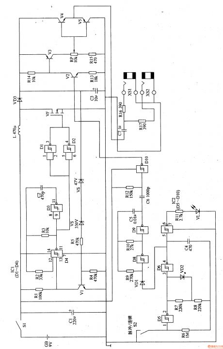
The circuit consists of high voltage making circuit, pulse making circuit and outputting circuit. (It is showed in picture 9-32.)
When S2 is turned on, the Electronic Pain Relieving Instrument works continuously. The 2Hz OSC does not work at all. The OSC outputs pulse continuously. And its working rate is about 10Hz. When you turn off S2 the Electronic Pain Relieving Instrument works intermittently. The OSC outputs pulse intermittently. Its working rate changes between 50Hz and 270Hz.
The pulse signal is amplified by V2-V5. The 2 poles on the outer side have pulse currency of low frequency. The pulse currency of low frequency stimulates the subcutaneous nurse and relieves pain. (View)
View full Circuit Diagram | Comments | Reading(626)
The electric timer circuit of ceiling fans
Published:2011/6/4 6:53:00 Author:qqtang | Keyword: electric timer, ceiling fans

The timer circuit consists of the power supply circuit, time delay control circuit and single steady trigger control circuit, see as figure 1.
In the circuit, the power supply circuit consists of the power supply switch C1, releasing resistor R1, voltage steady diode VS, rectifier diode VD and filter capacitor C2; the time delay control circuit consists of the NPN V, resistors of R2 and R3 and the capacitor C3; the single steady trigger control circuit consists of timer selecting switch S2, capacitors of C4 and C5, the time-based integrated circuit IC, resistors of R4-R8 and thyristor VT. (View)
View full Circuit Diagram | Comments | Reading(1245)
The typical application circuit of M708/M708L
Published:2011/6/6 0:09:00 Author:Seven | Keyword: typical application circuit
The typical application circuitThe typical application circuit of the remote control, which consists of M708 and M708L, is shown in the figure.
Figure:The typical application circuit of M708/M708L (View)
View full Circuit Diagram | Comments | Reading(580)
TDA7263AM-the integrated power amplifier circuit of dual channel audio
Published:2011/6/4 7:06:00 Author:qqtang | Keyword: power amplifier, dual channel audio

TDA7263AM is an integrated power amplifier circuit of dual channel audio which is produced by Philips Corp., and it is widely used in Haier, Hisense and Skyworth large color TV.1. Pin functionsTDA7263AM consists of two teams of audio power amplifier circuits with same functions, silence/mute circuit or standby control circuit, overheat protect circuit and over-pressure circuit. Its working voltage range is wide, the output power is big(25w for each channel).2.pin functions and dataTDA7263AM is in 11-pin single in-line package.
(View)
View full Circuit Diagram | Comments | Reading(394)
The internal circuit of M6M80014P
Published:2011/6/6 0:02:00 Author:Seven | Keyword: internal circuit
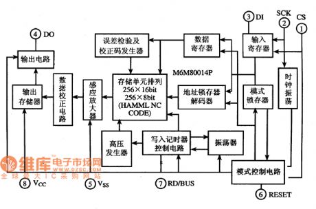
Function featuresM6M80014P includes the storage matrix, register, address latch/decoder, module control circuit, and high voltage generator, etc. Its internal circuit are shown in the figure.
Figure: the internal circuit of M6M80014P (View)
View full Circuit Diagram | Comments | Reading(381)
Electronic Pain Relieving Instrument (the 3rd)
Published:2011/6/6 8:15:00 Author:Felicity | Keyword: Electronic Pain Relieving Instrument (the 3rd)
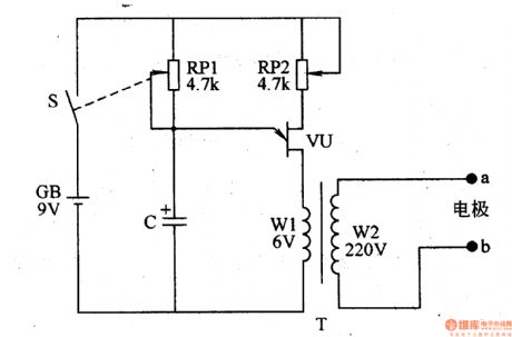
Work of the circuit
The circuit consists of potentiometer RG1 RG2, capacitor C, power switch S and pole A B. (It is showed in picture 9-33.)
Turn on switch S and the OSC starts working. The high voltage pulse is produced on the two ends of W2. The high voltage pulse is put on the pain area of the body by the poles. It can relieve the pain by stimulating the relevant acupoint or pain area.
Change the value of RG1 to change the frequency of OSC.
Change the value of RG2 to change the pulse voltage.
(View)
View full Circuit Diagram | Comments | Reading(826)
The multi-function electric point detector and therapeutic apparatus circuit
Published:2011/6/6 1:53:00 Author:Seven | Keyword: point detector, therapeutic apparatus
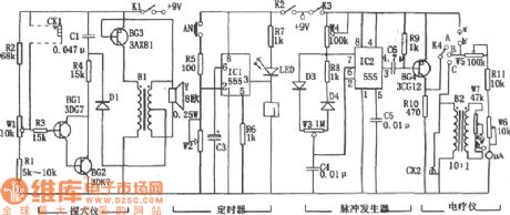
In the figure are the multi-function electric point detector and therapeutic apparatus circuit. The point detector and therapeutic apparatus consists of the point detecting circuit, timer, pulse generator and power amplifier output, etc. The point detecting circuit, which consists of BG1,BG2,R1~R4,W1,C1,BG3,B1 and so on, is factually an audio oscillator. If we insert two probes of two poles in the hole of CK1, then because the resistance of the point is low, or due to the low resistance that is caused by the ear illness, the frequency of the oscillator turns high; the longer the distance between the point and the probe is, the lower the frequency will be, so the point detection can be fulfilled. (View)
View full Circuit Diagram | Comments | Reading(502)
TD7101F-the integrated circuit of programmable preset frequency splitting
Published:2011/6/4 7:36:00 Author:qqtang | Keyword: frequency splitting, integrated circuit


TD7101F is a preset frequency splitter in the digital modulation system of low-voltage power supply, whose maximum working power is 250MHZ.1. Function features TD7101F includes the frequency splitting circuit, the frequency splitting preset circuit and other additional function circuit. As the frequency of FM signal is 108MHz, and it is added with a middle frequency of 10.8MHz, so the maximum frequency of FM is 118.7MHz, usually, such a high frequency can not work in CMOS/PMOS. The function of TD7101F is to split the frequency, so that it will be lower than the working frequency of the integrated circuit.
(View)
View full Circuit Diagram | Comments | Reading(472)
The broad range digital capacitance measuring instrument circuit
Published:2011/6/5 22:18:00 Author:Seven | Keyword: broad range, capacitance, measuring instrument
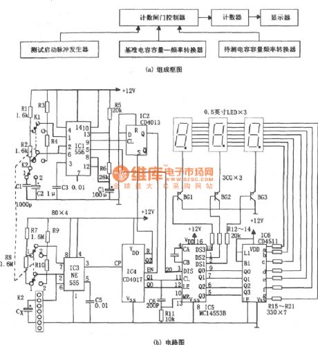
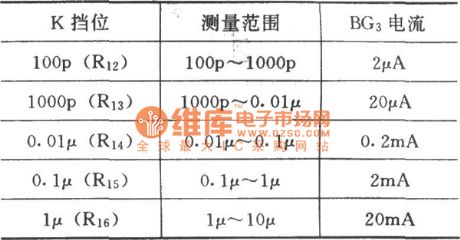
Pulse generator is a multi-resonate oscillator which consists of IC1(556), R1, R2, C1,R3, R4, C2 and so on, the oscillating frequency is f1= 1.44/(R1+2R2)C1, or f2=1.44/(R3+2R4)C2。The output pulse of 9-pin rises and the output terminal Q of D trigger IC2(CD4013) generates a low LEV, and the low LEV is added to the EN terminal of the counter IC4(cd4017), which makes the counter in the working state. The pulse output by the 5-pin controls the DIS pole of the 3 bit BCD counting circuit IC5(MC14553B). The capacitor volume under test --frequency shift circuit consists of R7,R8,IC3 and the capacitor Cx under test.
(View)
View full Circuit Diagram | Comments | Reading(650)
Electronic Massager (the 1st)
Published:2011/6/6 8:17:00 Author:Felicity | Keyword: Electronic Massager (the 1st)
Work of the circuit
The circuit consists of low frequency OSC and electronic outputting circuit. (It is showed in picture 9-34.)
Turn on the switch S and low frequency OSC starts working. IC1’s pin 3 outputs pulse signal. The signal controls the working condition of V andIC2. When the pulse signal is right V works. When the pulse signal is negative V does not work. And VL does not shine. W2 produces pulse currency of low frequency. The pulse currency of low frequency stimulates the relevant acupoint or pain area to massage.
(View)
View full Circuit Diagram | Comments | Reading(1658)
The simple coil turn number measuring instrument circuit
Published:2011/6/5 23:47:00 Author:Seven | Keyword: coil turn number, measuring instrument
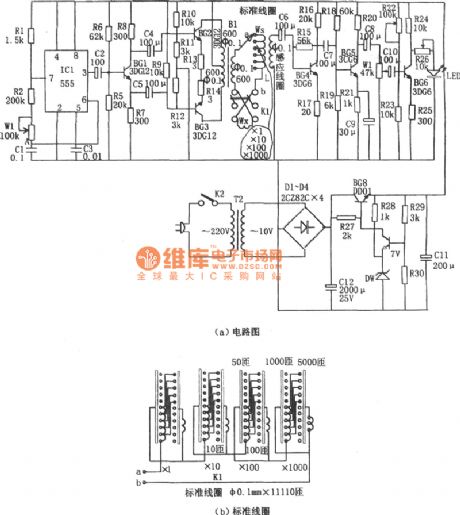
The measuring of the coil is used with magnet voltage comparing principle , i.e the coil Wx under test and the standard coil Ws are got through with a AC current I, if the two coils are connected in reversed-phase series, the total magnetomotive of them is Vm=(Ws-Wx)i. If Ws=Wx, then Vm=0, so the turn number of coil under test can be calculated by that of the standard coil. The pulse signal generator is a multi-resonate oscillator which consists of IC(555), R1, R2, W1 and CI, and its oscillating frequency is f=1.44/(R1+2R2+2Rw1)C1, the frequency of the parameter in the figure is 40~70Hz. Adjust the potentiometer W1 and make the oscillating frequency at 50z.
(View)
View full Circuit Diagram | Comments | Reading(695)
The circuit of transistor characteristic curve depicting instrument
Published:2011/6/5 22:04:00 Author:Seven | Keyword: transistor characteristic curve, depicting instrument

See as figure (a), the circuit consists of a sawtooth wave generator and a step wave generator. As depicting transistor characteristics needs two voltages, one the them is the step wave on b pole, by which a basic pole current is generated; the other is the sawtooth wave on C pole. The period is corresponding to the step wave, so that the output characteristic curve of the transistor can be depicted, i.e the characteristic curve of Ic-Vce. The sawtooth wave generator consists of the multi-resonate oscillator (IC(555),R1,R2 and C1) and the integration circuit(C2 and R3).
(View)
View full Circuit Diagram | Comments | Reading(716)
The pin arrangement of the M208B1 integrated circuit
Published:2011/6/5 23:51:00 Author:Seven | Keyword: pin arrangement, integrated circuit
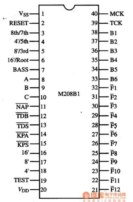
Figure: The pin arrangement of M208B1 (View)
View full Circuit Diagram | Comments | Reading(1979)
The crystal test circuit
Published:2011/6/5 21:51:00 Author:Seven | Keyword: crystal test
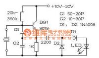
With some simple elements, we can make a crystal test circuit which can detect the frequency ranges 10kHz-100MHz, BG1 connects with a multi-resonate oscillator, after being detected by C3,D1 and D2, a voltage of upper-negative and lower-positive is got on the LED, which drives the LED to flow. If the crystal is broken, the LED won't glow. This circuit can be installed in a repairing power supply, leaving 2 holes for crystal detecting elements. Notes for assembling: the two wires led out from the crystal can be too close, or the amplitude will be highly reduced and the LED won't flow.
(View)
View full Circuit Diagram | Comments | Reading(669)
The multiple filter circuit of the single full-wave rectifier
Published:2011/6/5 21:38:00 Author:Seven | Keyword: multiple filter, single full-wave rectifier
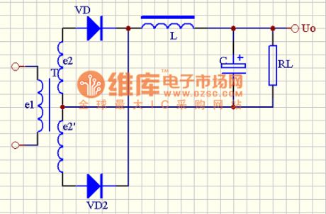
View full Circuit Diagram | Comments | Reading(395)
Multifunctional Motor Protector (1)
Published:2011/5/25 6:13:00 Author:Sue | Keyword: Multifunctional, Motor, Protector
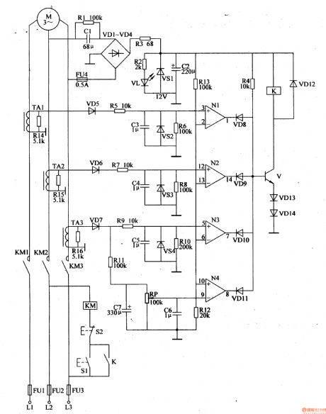
When the motor works well, N1-N3's in-phase input terminals have higher voltage than reference voltage. N4's opposite phase has a lower voltage than the reference voltage. N1-N4 output high level. VD8-VD11 are disconnected. V,VD13,VD14 are connected.
When the motor doesn't work well, V is disconnected and K is released.KM is released. M's working power will be cut off.
When the motor is overload, W's opposite phase will have a higher voltage than the reference voltage. N4 outputs low level and VD11 is connected, V is disconnected. K and KM are released. The motor's working power will be cut off. (View)
View full Circuit Diagram | Comments | Reading(415)
The auto-illuminance control system circuit
Published:2011/6/2 9:12:00 Author:Seven | Keyword: auto-illuminance control system

The following is an auto-illuminance control system circuit. This control system consists of 4 streams of photoelectric switch circuits. Take the first stream as an example, the light dependent resistor(LDR) is in a low resistance in the light, but it is a high resistance when the light is weak or it's dark outside. Therefore, when it's dark outside, the high voltage, which is got by the high-resistant RG, R1 and WI, flows through the NAND IC1-1(1/4 CD4011), and then it is imposed on 5-pin of IC2(555), which makes the 2-pin of IC2 to be offset due to the low LEV and the 2-pin is in a steady state, the 3-pin outputs a high LEV, the relay of J1 pulls in and relevant devices are glowing.
(View)
View full Circuit Diagram | Comments | Reading(504)
| Pages:1797/2234 At 2017811782178317841785178617871788178917901791179217931794179517961797179817991800Under 20 |
Circuit Categories
power supply circuit
Amplifier Circuit
Basic Circuit
LED and Light Circuit
Sensor Circuit
Signal Processing
Electrical Equipment Circuit
Control Circuit
Remote Control Circuit
A/D-D/A Converter Circuit
Audio Circuit
Measuring and Test Circuit
Communication Circuit
Computer-Related Circuit
555 Circuit
Automotive Circuit
Repairing Circuit