
Circuit Diagram
Index 1783
The high-speed absolute value amplifier circuit diagram
Published:2011/6/8 22:01:00 Author:leo | Keyword: The high-speed absolute value amplifier circuit diagram, LM318, HA2525

The picture 1 shows a high-speed absolute value amplifier circuit. The operating amplifier and diode form the ideal diode circuit which is used to detect communication signals. However, in the ideal diode circuit, rectified input voltage gives an effect directly to the frequency of operating amplifier and high frequency is limited. High speed operating amplifier, such as LM318, HA2525, μA715 and so on, can ensure an over 100kZ operating frequency. Operational Amplifier should be selected in the high-speed absolute value amplifier circuit. In this circuit, A1 uses HA2526 operational amplifier and also LM318. But the cut-off distortion of diode affects the high frequency operating, therefore, it takes VT1 and VT2 to form constant current source in this circuit. (View)
View full Circuit Diagram | Comments | Reading(1454)
The low-end current monitor circuit formed by AD8551
Published:2011/6/9 2:47:00 Author:leo | Keyword: The low-end current monitor circuit formed by AD8551, AD8551

The picture shows a low-end current monitor circuit formed by AD8551, which is used to detect the motor current or charging current. When detecting the current of the motor or rechargeable battery, high-end monitor is frequently used, which is usually used to detect the power sourcing current.
In this circuit, A1 adopts highly accurate operating amplifier AD8551 which uses +2.7 to +5V signal power source to operate. (View)
View full Circuit Diagram | Comments | Reading(1788)
electromotion model airplane remote control device
Published:2011/6/8 10:29:00 Author:Lena | Keyword: electromotion model, airplane, remote control


Electromotion model airplane remote control device consists of two-channel digital proportion driven circuit, servo circuit, power motor drive circuit etc.
(View)
View full Circuit Diagram | Comments | Reading(2671)
Phone ringing warner
Published:2011/6/8 10:43:00 Author:Lena | Keyword: Phone, ringing, warner


Phone ringing warner can cut-off music power supply which is playing now when a phone calling in ,to avoid bobbling phone. It consists of transmitter and receiver two parts. The transmitter circuit is shown in figure(a), the receiver circuit is shown in figure(b).
(View)
View full Circuit Diagram | Comments | Reading(733)
uPD550C (TV set) 4bit singlechip microprocessor circuit
Published:2011/6/6 9:31:00 Author:Lena | Keyword: 4bit, singlechip, microprocessor
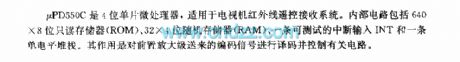
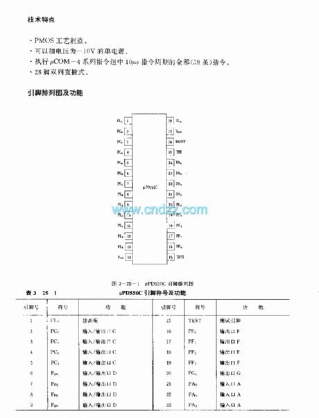
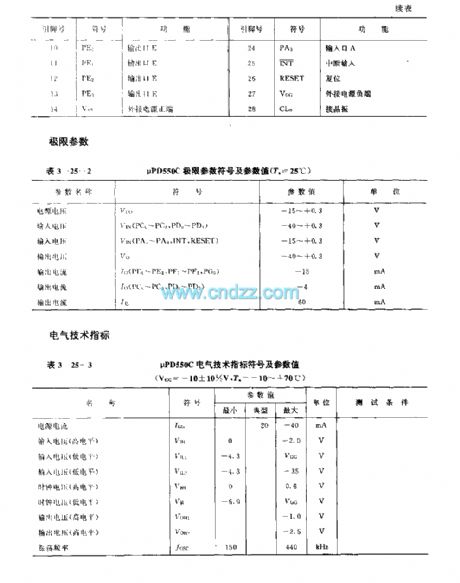
μPD550C is a 4-bit singlechip microprocessor applied to TV infrared remote control receiver system. Internal circuit includes 640×8bit real only memory(ROM), 32×4bit random access memory(RAM),a testable interrupt input INT and a single level stack. The function is encoding code signal sent by preamplifier and controlling related circuits.
Technology characteristicPMOS technics.A -10V single power supply can be added.Execute all the instructions(58 pieces) that period is 10μs inμCOM-4 series team.
(View)
View full Circuit Diagram | Comments | Reading(991)
The high input resistance amplifier circuit formed by FET
Published:2011/6/8 22:13:00 Author:leo | Keyword: The high input resistance amplifier circuit formed by FET

The picture 1 shows a high input resistance amplifier circuit. The picture 1(a) is the sourcing follower circuit formed by FET. The voltage gain of the follower: Av=gmRL/(l+gmRL); gm is mutual conductance; RL is sourcing load resistance. If Ac needs to be near 1, FET with bigger gm value is needed with the resistance value RL as big as possible. In order to increase the RL value, constant sourcing current formed by VT2 is adopted.
The picture1 (b) is the high input resistance circuit formed by FET. R1 is the grid offset deciding resistance. The current pass through R1 is usually very small. So the resistance is super high in the circuit.The Picture1 (c) is the circuit connected to operational amplifier. It is made up of two simple FET. RP1 is used to investigate the offset voltage. (View)
View full Circuit Diagram | Comments | Reading(1447)
ultrasonic sensor remote control circuit application example
Published:2011/6/9 7:49:00 Author:Lena | Keyword: ultrasonic sensor, remote control, application


、Piezoelectricity ceramic ultrasonic transducer(ultrasonic sensor)has small (View)
View full Circuit Diagram | Comments | Reading(1238)
315 remote control circuit
Published:2011/6/9 8:22:00 Author:Lena | Keyword: remote control, circuit


Early transmitters more usually use LC oscillator, but frequency excursion is more graveness. The appearance of sound-surface device solve the problem, the frequency stability is general same as crystal oscillator, but the base frequency can be hundreds of even thousands of MHz. Dispense with multiple frequency, this circuit is more simple than crystal oscillator circuit. These two are common transmitter circuits, because of using sound-surface device, these circuits work very stable. Even if hand antenna, sound-surface or other part, transmit frequency will not excursion.
(View)
View full Circuit Diagram | Comments | Reading(1514)
BA8105(electronic fan) infrared remote control receiving control circuit
Published:2011/6/9 8:50:00 Author:Lena | Keyword: infrared, remote control, receiving


BA8105 is a infrared remote control receive control integrated circuit applied to fans. In Combination of with BA5102, can realize channel infrared remote control.Technology characteristic and functionleakage trigger design can protection controlled silicon and reduce interference.Mis-trigger key self-protectionStrong wind, middle wind or weak wind control and strong wind startup functionThree selections: common wind, natural wind or sleep windTiming mode: 0.5、1、2、4 hour four-flight progression time, or 1、2、4 hour three-flight not progression time.
(View)
View full Circuit Diagram | Comments | Reading(642)
FCA84C640(TV) remote control microprocessor
Published:2011/6/8 10:18:00 Author:Lena | Keyword: remote control, microprocessor
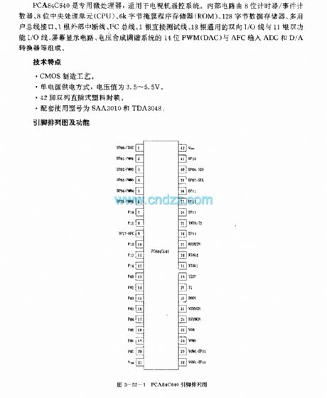
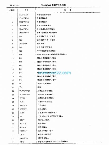
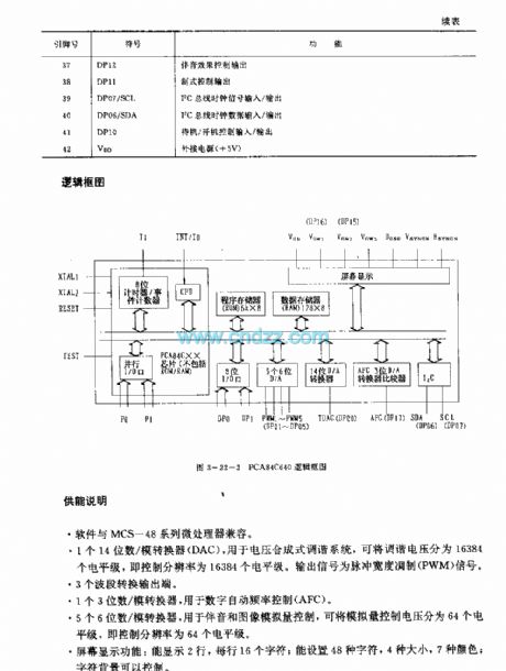
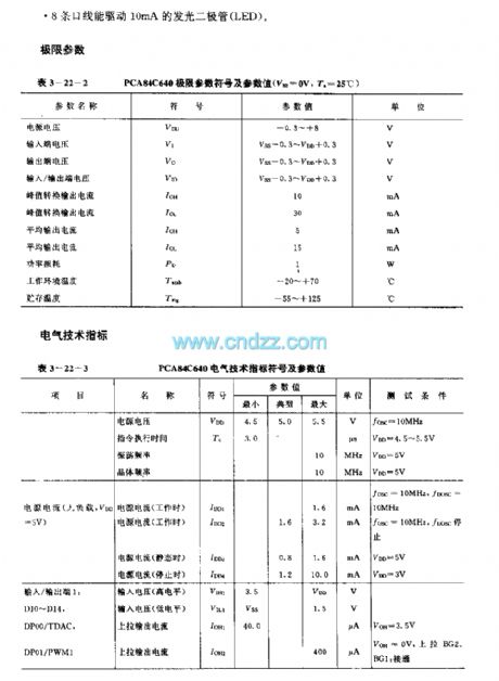
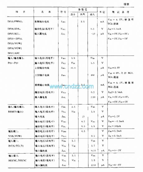
PCA84C640 is a special microprocessor applied to TV remote control system. Internal circuit consists of 8-bit counter/event counter, 8-bit central processing unit(CPU), 6k byte mask program memory(ROM), 128 byte data memory, multi-user bus line interface, 1 outside interrupt line, I2C bus line, 1 direct test line, 18 universal two-way I/O line and 11 two-function I/O line, screen display circuit, voltage synthesis tune system 14-bit PWM(DAC) and AFC input ADC and D/A converter etc.
(View)
View full Circuit Diagram | Comments | Reading(1134)
phone remote control monitor circuit
Published:2011/6/9 9:53:00 Author:Lena | Keyword: phone, remote control, monitor

Function characteristic1.remote control household appliances power on/off.2.remote control appliance power on, if delay auto cut-off.3.remote or local change password, simulate off-hooking ring times and all set functions of remote-control unit.4.2-way contact output(connect 220V power supply socket),1-way direct current output(12V),1-way level output(two positive, negative output ends, which can direct connect related appliance control end ).5.second function setting, add remote control monitor function.
(View)
View full Circuit Diagram | Comments | Reading(750)
M50460—001P/FP (TV)infrared remote control transmitting microprocessor
Published:2011/6/1 9:37:00 Author:Lena | Keyword: infrared, remote control, transmitting, microprocessor
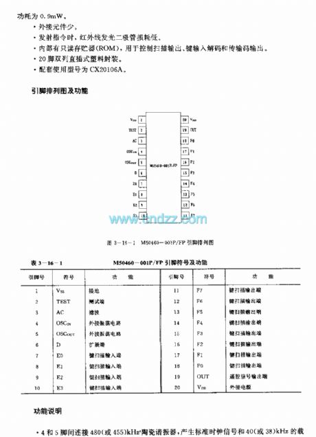
M50460-001P/FP are infrared remote control transmitting microprocessors used in TV etc. The only difference between M50460-001P and M50460-001FP is the shape.
technology features
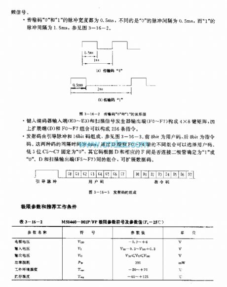
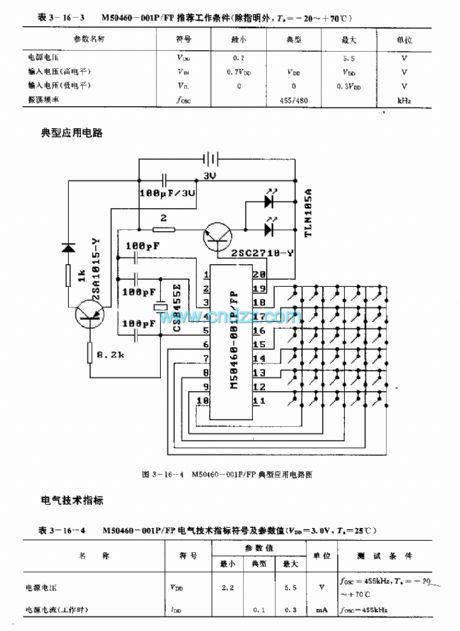
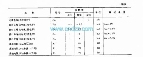
Single voltage source, voltage range is 2.2 to 5.5V.Power loss is low. When at Readiness, typical power loss is 3nW,max loss is 3μW; at natural work, the max loss is 0.9mW.A few of external elements Transmitting signals, the infrared LED power loss is low.Internal circuit includes Read-only memory, used to control scan output, key input decode and transmission code output.20 pins dual in-line plastic package.
(View)
View full Circuit Diagram | Comments | Reading(668)
LM39U(annunciators and self-control devices) singlechip temperature control circuit
Published:2011/6/1 9:38:00 Author:Lena | Keyword: annunciators , self-control devices, singlechip, temperature control


LM3911 is a singlechip temperature control integrated circuit applied to annunciators and self-control devices etc. Internal circuit consists of temperature sensor, operational amplifier and reference voltage source etc.
Technical characteristicOutput voltage is inproportion to the thermodynamics temperature, the sensitivity is 10mV/K.Internal reference voltage source regulation value is 6.8V.Add appropriate current-limiting resistance, which can work at volt d.c above 7V.Internal sensor uses transistor e-b node voltage differences that work at different current density as temperature sensing element.Measurement temperature range is -25~+85℃.
(View)
View full Circuit Diagram | Comments | Reading(575)
Overvoltage Detection Circuit Diagram formed by LTC1541 and Others
Published:2011/5/21 21:34:00 Author:leo | Keyword: Overvoltage Detection Circuit Diagram formed by LTC1541 and Others, 1N4005, ZTX458, 100K, 300K, 600V, LTC1541, 240V
As the picture shows, this is a overvoltage detection circuit. It is applied to detect the overvoltage in any power supply circuit with a detection scale from 3 V to hundreds of voltage. Besides, it can also be used to lock detect the voltage which can detect 30μs transient overvoltage peak pulse. Under the common condition, the current consumption of this circuit will be under 25μA. So it is the best voltage control circuit in the battery power supply system.
LTC1541 applied in this circuit is a kind of integrated circuit which contains a comparator A1 that has a small power compensation, operating amplifier A2 as well as UREF with the referred voltage of 1.20 V. This circuit demands a maximum of 13μA. (View)
View full Circuit Diagram | Comments | Reading(615)
M491 (TV)infrared remote control receiving microprocessor
Published:2011/6/1 9:41:00 Author:Lena | Keyword: infrared, remote control, receiving, microprocessor
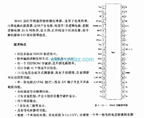
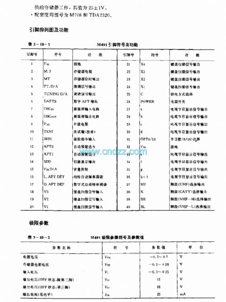
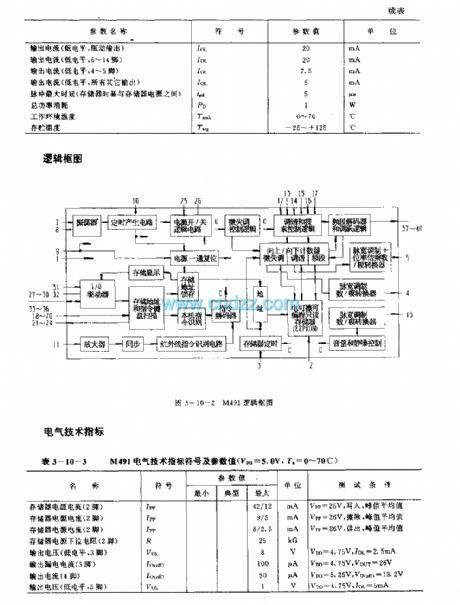
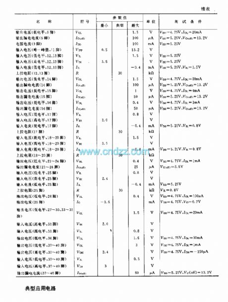
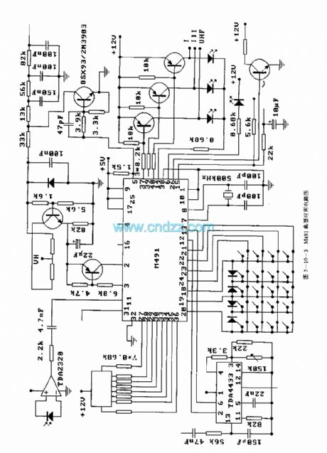
M491 is an infrared remote control receiving microprocessor applied to TV etc. Internal circuit is composed by oscillator, timing generating circuit, power supply on/off logic circuit, control logic circuit, D/A converter, amplifier, infrared instruction Identification circuit, instruction decoder and I /O driver etc.
Technical characteristictwo-poly silicon NMOS manufacturing Technologypulse code modulation transmitting method, duty cycle is 0.15%.A EEPROM memory, and simple external circuit.Store 16 preelection program information13-bit voltage synthesis tuner, which has three functions: manual tune, auto tune and auto preplace.
(View)
View full Circuit Diagram | Comments | Reading(1056)
Digital Meter Panel Circuit Diagram made up of PIC16C711 and Others
Published:2011/5/20 22:13:00 Author:leo | Keyword: Digital Meter Panel Circuit Diagram made up of PIC16C711 and Others, PIC16C711

As the picture shows, this is a electrical digital meter panel circuit. As a 8 bits A/D converter, PIC16C711 has two input ports. Among them, AD0 is voltage input port and AD1 is scale selecting input port. If AD1 is connected to ground, it will show a scale of 0.00 V to 5.10 V with resolution of 20 mV. If AD1 is connected to 2.5V voltage, it will show a scale of 00.00 V to 12.75 V with the resolution of 50 mV. If AD1 is connected to 5 V, it will show a scale of 00.0 V to 25. 5 V and the resolution will be 100 mV. Under the common condition, PIC16C711 display accuracy is ±1/2LSB. It can drive four seven-port LED at the same time and only one LED can be lighted at one time. The input voltages of PIC16C711 are 5 V, 12 V and 25 V. (View)
View full Circuit Diagram | Comments | Reading(4914)
M501245A(TV) infrared remote control receiving microprocessor
Published:2011/6/1 9:40:00 Author:Lena | Keyword: infrared, remote control, receiving, microprocessor
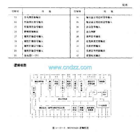
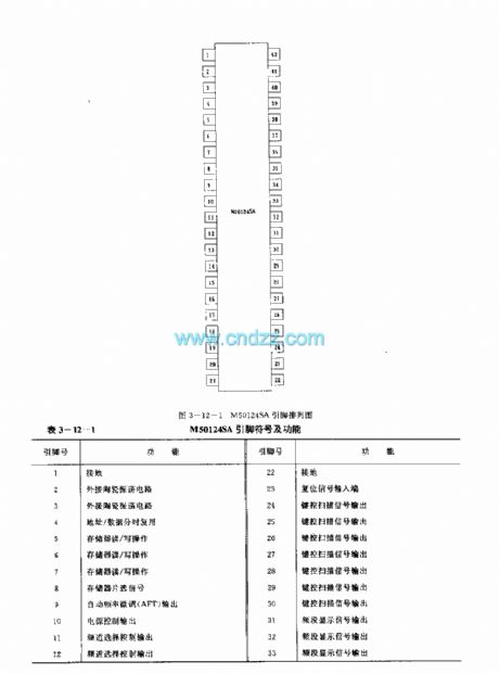
M50124SA is an infrared remote control receiving microprocessor which is applied to TV etc. Internal circuit is composed by oscillator, remote control signal processing circuit, AFT control circuit, power supply control circuit, channel selection control circuit, main switch input circuit, state control circuit, mute control circuit, key control decoder, reset input circuit, display control circuit, receiving code detector, CPU, ROM/RAM, D/A converter and instruction decoder etc. Package type is 42-pin dual-in-line plastic package.
(View)
View full Circuit Diagram | Comments | Reading(636)
KA2311 (toy) wireless remote control receiving control regulation circuit
Published:2011/6/1 9:39:00 Author:Lena | Keyword: wireless, remote control, receiving, regulation


KA2311 is a wireless remote control receiving control regulation single integrated circuit which is applied to toys etc. Internal circuit consists of receiving amplifier, Miller integrator, duty cycle integrator, buffer, comparator and driver etc.
Technical characteristicWide power supply range, the value is 3-18V.Few external elements Integrated circuit with turbo circuitWhen the toy stops, it can turn left or right16-pin DIP packageRelated type is KA2312
(View)
View full Circuit Diagram | Comments | Reading(2109)
Current Detection Circuit Diagram made up of LM311 and Others
Published:2011/5/20 22:42:00 Author:leo | Keyword: Current Detection Circuit Diagram made up of LM311 and Others, LM311

As what is shown in the picture, this is a current detection circuit diagram which is made up of LM311 and others. In this circuit, when the input control signal of the screen grid VT1 is in high level, it will use VT1 as the current detector. When the armature of DC electro-motor is turning, the commutator lug of brush shorts suddenly, which generates current pulses. The current pulses come through RDS of VT1 and are changed to voltage signals. Then the voltage signals are AC-coupled when passing through capacitor C1 and reach non inverting input port of comparison unit. C2 is used as filter which can make A1 output smooth wave shape that can be used in combination with pin 5 and pin6 to sharp the edge outputted by clock.
(View)
View full Circuit Diagram | Comments | Reading(1265)
KA2306A (toy)wireless remote control receiving control regulation circuit
Published:2011/6/1 9:11:00 Author:Lena | Keyword: wireless, remote control, receiving, regulation


KA2306A is a wireless remote control receiving control regulation single integrated circuit, applied to toys etc. Internal circuit consists of receiving amplifier, Miller integrator, buffer and voltage regulator etc.
Technical characteristicWide power supply range, the value is 3-18V.The current is small when at rest, the typical value is 10.5mAFew external elementsThe circuit has three functions, go ahead, stop and fall back.Integrated circuit has turbo circuit and voltage regulator served for super regenerative circuit.16-pin DIP package
(View)
View full Circuit Diagram | Comments | Reading(524)
| Pages:1783/2234 At 2017811782178317841785178617871788178917901791179217931794179517961797179817991800Under 20 |
Circuit Categories
power supply circuit
Amplifier Circuit
Basic Circuit
LED and Light Circuit
Sensor Circuit
Signal Processing
Electrical Equipment Circuit
Control Circuit
Remote Control Circuit
A/D-D/A Converter Circuit
Audio Circuit
Measuring and Test Circuit
Communication Circuit
Computer-Related Circuit
555 Circuit
Automotive Circuit
Repairing Circuit