
Circuit Diagram
Index 1791
TTS-200 temperature control thyristor basic application circuit
Published:2011/6/9 1:51:00 Author:Christina | Keyword: temperature control, thyristor, basic application

The basic application circuit of the temperature control thyristor is as shown in the figure. The RcA is the switch temperature control resistance, you can get different switch temperature by selecting different resistance of the RGA. VD is the operating voltage. When the temperature is lower than the switch temperature, the temperature control thyristor is in the cut-off state, VD port outputs the low electrical level; when the temperature reaches or exceeds the switch temperature, the temperature control thyristor conducts, the VD port outputs the high electrical level. It should be noted that the operating voltage VD has the relationship with the switch temperature, in order to ensure the stability of the temperature switch, VD needs to use the regulation measures.
Figure: The TTS-200 temperature control thyristor basic application circuit (View)
View full Circuit Diagram | Comments | Reading(697)
MC3357 small power frequency modulation intermediate frequency integrated circuit
Published:2011/6/9 2:03:00 Author:Christina | Keyword: small power, frequency, modulation, intermediate frequency, integrated circuit


The MC3357 is designed as one kind of small power frequency modulation intermediate frequency integrated circuit that is produced by the MOTOROLA company, and it can be used in the FM amplifier circuit of the FM duplex communication equipments.
1.Features
The MC3357 is composed of the oscillator circuit, the mixer circuit, the noise suppression and hysteresis circuit, the active filter amplifier circuit, the amplitude limit amplifier circuit, the demodulator circuit and other subsidiary function circuits.
2.Pin functions and data
The MC3357 has two kinds of package: one is the 16-pin dual-row DIP package; another is the 16-pin small SMD package that can be used in the surface installation technology, the pin functions and data is as shown in the table.
The pin functions and data of the MC3357
3.Typical application circuit
The internal circuit block diagram and the typical application circuit of the MC3357 is as shown in the figure.
The internal circuit block diagram and the typical application circuit of the MC3357 (View)
View full Circuit Diagram | Comments | Reading(1176)
The electric thermos circuit (01)
Published:2011/6/3 0:13:00 Author:Seven | Keyword: electric thermos

Figure 6-9 the Haima SHEA-3200 electric thermos circuit (View)
View full Circuit Diagram | Comments | Reading(1059)
The electric thermos circuit (02)
Published:2011/6/3 0:11:00 Author:Seven | Keyword: electric thermos

View full Circuit Diagram | Comments | Reading(700)
The headphone diode receiving phone
Published:2011/6/3 0:09:00 Author:Seven | Keyword: diode receiving phone
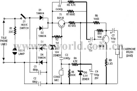
View full Circuit Diagram | Comments | Reading(394)
the emitting circuit
Published:2011/6/3 0:07:00 Author:Seven | Keyword: emitting circuit
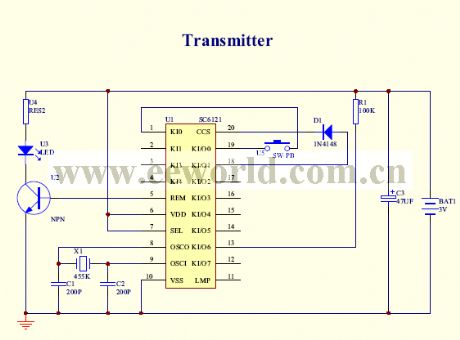
View full Circuit Diagram | Comments | Reading(372)
The photocoupler-replaced audio transformer circuit
Published:2011/6/3 0:18:00 Author:Seven | Keyword: audio transformer
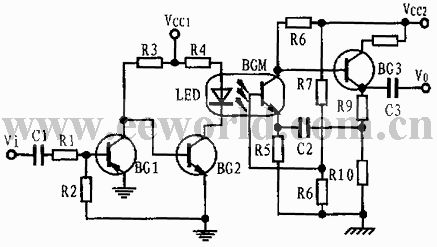
View full Circuit Diagram | Comments | Reading(640)
The gas water heater circuit
Published:2011/6/3 0:52:00 Author:Seven | Keyword: gas water heater

View full Circuit Diagram | Comments | Reading(2811)
The thermocouple AD switch circuit
Published:2011/6/3 1:06:00 Author:Seven | Keyword: thermocouple, AD switch circuit
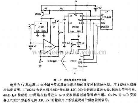
Figure 1-7 the thermocouple temperature control circuitThis is a temperature control circuit of 5V single power supply and 12 bit cold pole compensation, which has the functions of shutting-off. The supervision is done by a J thermocouple. LT1025A is a compensation circuit of the thermocouple cold pole, LTC1050 is the wave-cutting computing amplifier which is used to magnify the signals. The RC net of 47KΩ and 1μF can filter noises when the signal is coming in to the A/D converter. LT1297 is the A/D converter, LTC1257 is the reference power supply, and the output of LTC1257 is the temperature control signal in system supervision. (View)
View full Circuit Diagram | Comments | Reading(906)
The thermocouple temperature/frequency converter circuit
Published:2011/6/3 1:20:00 Author:Seven | Keyword: thermocouple, temperature/frequency converter

The output pulse of I3 drives the DIN-pin of LTCI146, and GNDI is connected with I3. The output of DOUT and TIL are compatible with signals. The maximum consumption current of the circuit is 460μA, and it is allowed to use the 9v power supply. LT1025 is the thermocouple cool pole compensator, LTC1049 is a low-power computing amplifier which contains capacitors, and LTC1146 is an integrated signal separating circuit. (View)
View full Circuit Diagram | Comments | Reading(962)
The thermistor temperature collecting circuit
Published:2011/6/3 1:44:00 Author:Seven | Keyword: thermistor, temperature collecting
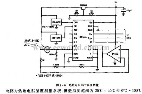
Figure 1-6 the thermistor of temperature measuringThis is a thermistor temperature measuring system, whose covering temperature ranges are 20℃~40℃ and 0℃~100℃. (View)
View full Circuit Diagram | Comments | Reading(501)
The radio circuit of frequency LED display (1)
Published:2011/6/3 23:27:00 Author:Seven | Keyword: radio circuit
View full Circuit Diagram | Comments | Reading(513)
The switch steady power supply circuit consisting of DN-25 single chip switch regulator
Published:2011/6/5 2:28:00 Author:Seven | Keyword: power supply, single chip

This is a switch steady power supply consisting of DN-24 integrated circuits. DN-25 is a power supply element of the single chip steady regulator, which is suitable for making the steady power supply of intermediate current and wide voltage range. Its main function parameters are as follows: input voltage is VIN=3~40V, output voltage is Vo=1.25~24V(can be continuously adjusted), maximum output current IOM=1A, maximum output power POM=36W, loading short limiting current IOSH≤1.1A. DN-25 is in 8-pin dual in-line package(DIP-8), whose internal circuit includes:(1) oscillator(OSC); (2)R-S trigger; (3) output switch.
(View)
View full Circuit Diagram | Comments | Reading(787)
The music fancy lantern controller circuit
Published:2011/6/2 8:17:00 Author:Seven | Keyword: music fancy lantern, controller circuit

See as the following figure, this is a music fancy lantern controller circuit. The controller consists of sound/power switch and amplifier circuit, clock pulse generator, counting circuit and control circuit, etc. The microphone MIC switch sound signal into power signal, and then the signal is added to 4-channel analog switch CD4066(IC3) after it has been magnified by BG1~BG3. The clock pulse generator consists of IC1(555), W1, R1, R2, D1, C1 and so on, the period of signal generating is T=0.693(Rw1+R1+R2)C1, the period corresponding to the figured parameter ranges 0.5~5s, of which the 3-pin output of 555 is added to IC2 as the CP pulse.
(View)
View full Circuit Diagram | Comments | Reading(515)
The automobile supervision circuit
Published:2011/6/3 2:21:00 Author:Seven | Keyword: automobile, supervision circuit
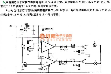
This circuit is used to supervise the automobile power supply of 12V. If the voltage ranges 12~14.5v, it is normal; if the voltage is lower than 12v or higher than 14.5v, there will be indicators glowing. A1 and A2 are the indicator comparator, which are used to adjust the relays of W1 and W2. When the voltage of automobile power supply is higher than 14.5v, the indicator of B is lighting; if it is lower than 12v, the indicator of A is lighting; when it is normal, neither of the indicators is glowing.
(View)
View full Circuit Diagram | Comments | Reading(406)
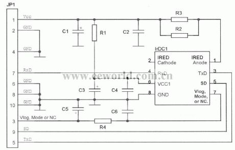
The power supply circuit of infrared emitting/receiving
Published:2011/6/3 0:50:00 Author:Seven | Keyword: power supply, infrared emitting/receiving
View full Circuit Diagram | Comments | Reading(394)
Counter-type Peak Hold Circuit Diagram
Published:2011/6/9 4:06:00 Author:Vicky | Keyword: Counter-type Peak Hold,
(View)
View full Circuit Diagram | Comments | Reading(984)
Electronic Tuner Circuit Diagram
Published:2011/6/9 4:04:00 Author:Vicky | Keyword: Electronic Tuner,

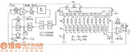
Tuner is a commonly seen standard sound calibrator. The tuning fork is usually made of metal. Beat it by hand to make it give out audio signal of 440Hz, and calibrate it by comparing with the calibrated sound. Electronic tuner is a sound calibrator made of electronic component. Electronic tuner is easier and more accurate than metal tuning fork, and what’s more, it can work continuously. The circuit principle is as shown in the picture. (View)
View full Circuit Diagram | Comments | Reading(827)
circuit of improving linearity of photoelectric isolation device
Published:2011/6/8 7:09:00 Author:chopper | Keyword: linearity, photoelectric isolation device
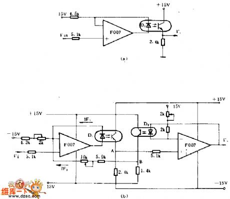
We can improve the linearity of transmission of photoelectric couplers markedly by using inverse feedback.In the picture a,D1 is in the feedback path,the current through D1 will vary linearly with V1 strictly.The shortage of this circuit is that it don't consider the non-linear relation between current transmission of photoelectric couplers and operating current.Thus,careful selection is necessary as well as adjusting device.In the picture b,the circuit adds the second order feedback in order to improve the linearity.The gain frequency of the circuit is between 0~30KHZ,and the dynamic range is -8~+8V,nonlinear distortion(when it is ±8V)is less than 0.5%,weeping sound is less than 1mV,common mode voltage is more than 250V.
(View)
View full Circuit Diagram | Comments | Reading(466)
Infrared Sphygmograph Circuit Diagram
Published:2011/6/9 4:09:00 Author:Vicky | Keyword: Infrared Sphygmograph Circuit,
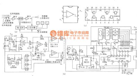
The so-called infrared sphygmograph means that the sensor that it uses to collect the signals is infrared sensor. Circuit is as shown in the picture. (View)
View full Circuit Diagram | Comments | Reading(695)
| Pages:1791/2234 At 2017811782178317841785178617871788178917901791179217931794179517961797179817991800Under 20 |
Circuit Categories
power supply circuit
Amplifier Circuit
Basic Circuit
LED and Light Circuit
Sensor Circuit
Signal Processing
Electrical Equipment Circuit
Control Circuit
Remote Control Circuit
A/D-D/A Converter Circuit
Audio Circuit
Measuring and Test Circuit
Communication Circuit
Computer-Related Circuit
555 Circuit
Automotive Circuit
Repairing Circuit