
Circuit Diagram
Index 1788
555 simple seven color lamp circulation control circuit
Published:2011/5/21 5:05:00 Author:TaoXi | Keyword: simple, seven color lamp, circulation control
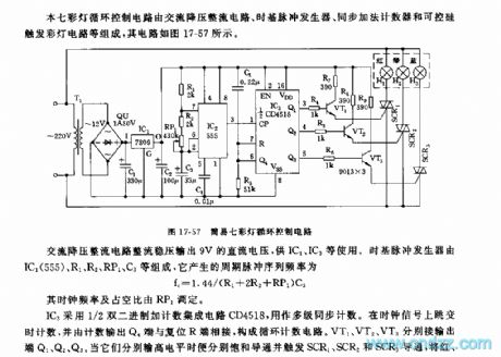
This seven color lamp circulation control circuit is composed of the DC step-down rectifier circuit, the time base pulse generator, the synchronous addition counter and the SCR trigger color light circuit, the circuit is as shown in figure 17-57.
The IC3 uses the 1/2 double binary adding & counting integrated circuit CD4518 as the multi-level synchronous counter. If you jump the time counting on the clock signal and connect the counting output terminal Q4 with the reset terminal R, so you constitute the circulation technology circuit. VT1, VT2, VT3 respectively connect to the output port Q1,Q2,Q3. The alterable colour unit is composed of the red, green, blue gezer lamp.
(View)
View full Circuit Diagram | Comments | Reading(446)
555 "happy birthday to you" electronic candle circuit
Published:2011/5/22 3:09:00 Author:TaoXi | Keyword: happy birthday to you, electronic candle
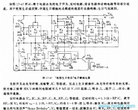
As the figure 17-47 shows, the whole circuit is composed of four parts: the optical electronic switch, the timing circuit, the voice circuit and the audio circuit, and it can be used in applications of birthday congratulation or celebration.
The optical switch is composed of the optical fiber, the light sensitive tube and the IC1.etc. When you light up the birthday candle, the light beam which is transmitted by the optical fiber reduces the interelectrode resistance of the phototransistor 3DU3 lower than dozens of ohms, 555 starts up, J1 closes, J1-1 turns off and J1-2 closes, the circulation path is connected.
The timing circuit is composed of the IC2,IC3,R2,RP2,C3,R4,RP3,C5. The timing time td=1.1(R+RP)C.
(View)
View full Circuit Diagram | Comments | Reading(1313)
555 toilet floodlight and ventilator automatic control circuit
Published:2011/5/21 4:32:00 Author:TaoXi | Keyword: toilet floodlight, ventilator, automatic control

The electronic switch is composed of the CK-4 type magnetic control switch and the VT1,R1,R2. When the bathroom door closes, the permanent magnet ZT and the reed pipe GA get close to separate the two touch tablets of GA, VT1 cuts off, pin-2 of IC has the high level voltage, 555 is in the reset state, J releases, the ventilation fan and light has no power. When someone gets into the bathroom and opens the door, the ZT and GA are seperated, VT1 conducts, 555 sets, J closes to close the J1-1 and J1-2, the ventilation fan gets the power to work, the light turns on. The power-on time depends on the delay time of the 555 homeostasis circuit td=1.1R3C2, the parameter in the figure is about 1 minute, you can change it by changing the R3C2 time constant.
(View)
View full Circuit Diagram | Comments | Reading(1280)
555 color amplification photo time exposure and acousto-optic alarm device
Published:2011/5/24 2:51:00 Author:TaoXi | Keyword: color amplification, photo, time exposure, acousto-optic, alarm
Related components PDF download:
NE555VT66A21S9013
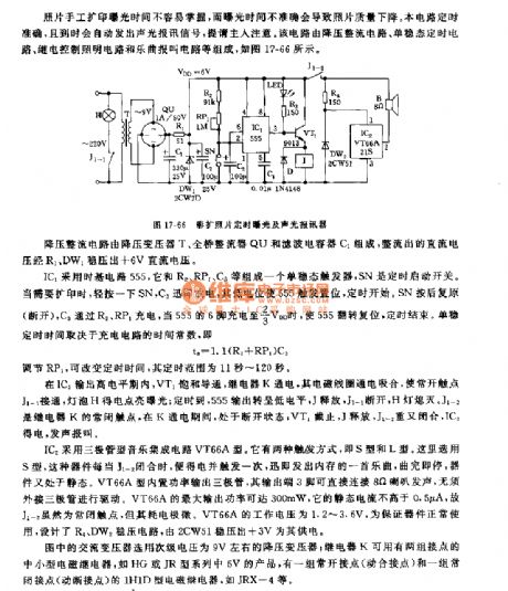
IC2 uses the audion type music IC VT66A. It has two kind of trigger mode: S mode and L mode. Here we use the S mode, this device will get the electricity and trigger for one time if the J1-2 closes, it sends out a song in the memory, after playing, this device will be in the static. The VT66A mode has the built-in power output transistor, the output port pin-3 can be connected with the 8 ohm speaker to send out voice, and there is no need to connect the external audion to drive. VT66A's maximum output power is 300mW, it's static current is less than 0.5 uA.
(View)
View full Circuit Diagram | Comments | Reading(439)
555 color photo printing & washing instrument circuit
Published:2011/5/20 8:05:00 Author:TaoXi | Keyword: color photo, printing, washing, instrument
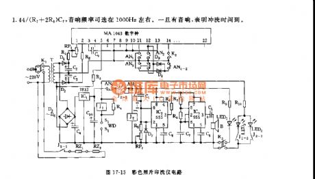
As the figure shown, the printing & washing instrument is composed of the temperatrure controller, the washing timer and the timing buzzer.etc. The temperature control range is below 50℃, also it is free to adjust; the temperature control accuracy is +/-0.5℃; the timing time is 2 minutes 45 seconds +/- 1 sec; the heating time is 1 hour.
The washing timing buzzer is composed of the IC2 and IC3, there is no need to adjust the time before using. The start timing circuit is composed of the IC2(555) and R5, RP2, C1, the timing time is td=1.1(R5+RP2)C1.
(View)
View full Circuit Diagram | Comments | Reading(466)
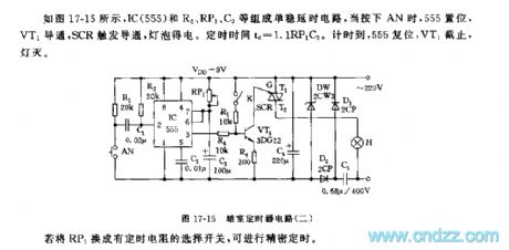
555 darkroom timer circuit (2)
Published:2011/5/24 2:50:00 Author:TaoXi | Keyword: darkroom, timer
Related components PDF download:
NE5553DG12
As the figure 17-15 shows, as the figure 17-15 shows, the monostable delay circuit is composed of the IC(555) and R2, RP1, C3.etc, when you press AN, 555 sets, VT1 conductd, the SRC trigger the conduction, and the lamp bulb gets the power. The timing time td=1.1RP1C3. When the time is up, 555 resets, VT1 cuts off, the light turns off.
If we changes the RP1 into the select switch with timing resistance, we can get the accurate timing.
(View)
View full Circuit Diagram | Comments | Reading(837)
Internal Circuit Block Diagram of LN8363D/DH Integrated Circuit
Published:2011/6/9 3:49:00 Author:Vicky | Keyword: LN8363D/DH Integrated Circuit,

Functions and Characteristics
The interior of LM8363D/DH integrated circuit is mainly composed of blanking circuit, frequency-dividing circuit and various counters and so on. LM8363D/DH integrated circuit has two warning systems and can display month, date (can be read by the pressing the key of “nap input”) and time. LM8363D/DH integrated circuit can preset sleep timer of 59min. The internal circuit block diagram of LM8363D/DH integrated circuit is as shown in the picture. (View)
View full Circuit Diagram | Comments | Reading(793)
Winding Machine Electronic Counter Circuit Diagram
Published:2011/6/9 3:50:00 Author:Vicky | Keyword: Winding Machine Electronic Counter,
Winding machine is one of the most commonly used tools in electrical industry. Traditional winding machine usually adopts mechanical counter. Therefore due to the wear caused by mechanical drive, the accuracy of counting cannot be guaranteed. When using the photoelectric sensor as the trigger flip-flop, due to the non-contact and high sensitivity, the accuracy of winding is high improved. This counter also has the function of addition and subtraction, and owns the unique advantage of being more convenient and accurate for error-correcting. The circuit composition diagram is as shownin the picture. (View)
View full Circuit Diagram | Comments | Reading(1650)
Electronic Sphygmograph Circuit Diagram
Published:2011/6/9 4:10:00 Author:Vicky | Keyword: Electronic Sphygmograph,
Sphygmograph and cardiotachometer are in fact two different sayings of one tester, and the difference of the two lies in the different sampling position. Cardiotachometer takes sample from breast, while sphygmograph from wrist. The following that we are going to introduce is electronic sphgmograph, and the circuit composition is as shown in the picture. (View)
View full Circuit Diagram | Comments | Reading(1137)
Quick Cardiotachometer Circuit Diagram
Published:2011/6/9 4:13:00 Author:Vicky | Keyword: Quick Cardiotachometer,

Cardiotachometer and frequency meter in fact belong to one sort of measure instrument. The difference is that the time gate of cardiotachometer is 1min, but not 1s. As to one measure instrument, measuring time of 1 min is long and hard to guarantee the precision. Therefore, alternate measuring is necessary, which meets the requirement of quickness and precision.The aboved picture is cardiotachometer circuit, and it can match the requirement of quickness and precision. (View)
View full Circuit Diagram | Comments | Reading(1664)
Typical Applied Circuit Diagram of LM1876 Integrated Circuit
Published:2011/6/9 4:14:00 Author:Vicky | Keyword: LM1876 Integrated Circuit, LM1876

LM1876 integrated circuit has three working mode: stand-by, squelch, and running. The current dissipation of stand-by is just 4.2mA. The power can be supplied by both positive and negative power. The typical applied circuit is as shown in the picture.
Internal circuit of LM1876 integrated circuit mainly include low-voltage protection circuit, over-power protection circuit, over-heat protection circuit, two power preamp circuits of the same function, two squelch control circuits of the same function , two stand-by control circuits of the same function , and power supply processing circuit of the same circuit and so on. (View)
View full Circuit Diagram | Comments | Reading(4263)
Digital Electronic Clock Calibrator Circuit Diagram
Published:2011/6/9 4:15:00 Author:Vicky | Keyword: Digital Electronic Clock Calibrator,

(View)
View full Circuit Diagram | Comments | Reading(1270)
Bicycle Speed Ometer Circuit Diagram
Published:2011/6/9 4:16:00 Author:Vicky | Keyword: Bicycle Speed Ometer,

Bicycle Speed Ometer (View)
View full Circuit Diagram | Comments | Reading(1010)
Typical Applied Circuit of LM1203 Integrated Circuit
Published:2011/6/9 4:16:00 Author:Vicky | Keyword: LM1203 Integrated Circuit,

Typical applied circuit of video small-signal processing which is composed of LM1023 integrated circuit is shown as in the picture.
Hint: If the character is lack of color, the raster is white after make it brighter, and if the signal wire, input circuit and output circuit are normal under such circumstance, then generally speaking, this failure is caused by the damage of LM1203. (View)
View full Circuit Diagram | Comments | Reading(2096)
Analog Capacitance Admeasuring Device Circuit Diagram
Published:2011/6/9 4:23:00 Author:Vicky | Keyword: Analog Capacitance Admeasuring Device, CD4013
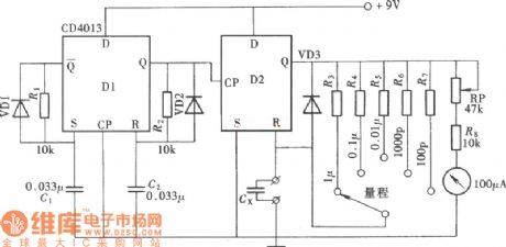
The picture is the circuit of analog capacitance admeasuring device. Use a double-D trigger, CD4013, and use one trigger of the double-Drigger, CD4013, together with a tested capacitance to constitute a monostable trigger to enable it to generate output pulse. The pulse width of this output pulse and the average current value is in proportion to the capacity of the tested capacitance. Use another one trigger of CD4013 to constitute a multivibrator to generate trigger pulse. A piece of IC can be used to constitute a simplified capacitance tester. The measurement range is l00pF~lμF. (View)
View full Circuit Diagram | Comments | Reading(1041)
Digital Frequency Meter Circuit Diagram
Published:2011/6/9 4:17:00 Author:Vicky | Keyword: Digital Frequency Meter,

(View)
View full Circuit Diagram | Comments | Reading(4182)
Capacitance Identification Device Circuit Diagram
Published:2011/6/9 4:22:00 Author:Vicky | Keyword: Capacitance Identification Device,

Capacitance identification device is not used to measure the capacity of the capacitor, but to identify whether the capacitor is good or bad, and whether it can be used, that is, whether there is short circuit or circuit break in the capacitor. It provides quality guarantee for making the circuit and reduce the unnecessary troubles. The circuit composition as is shown in the picture. This device can identify capacitors whose capacity are from 1pF to 1μF 1. (View)
View full Circuit Diagram | Comments | Reading(886)
The auto door control circuit
Published:2011/6/10 2:20:00 Author:qqtang | Keyword: auto door, control circuit

In the figure is the auto door control circuit. The human body movement detection is done with the new heat infrared probe module HN911. VT1 is the time delay control, by adjusting potentiometer RP1, the delaying time can be changed. The photocoupler MOC3020 is functioning as the D/A current separator. When there is no one walking, HN911 output terminal 1-pin is in a low LEV, VT1 controls the signal output, the dual-way thyristor Vh is closed, the loading motor is not working, and the gate is in the closed state. When someone is getting close to the auto gate, HN911 is detecting the infrared energy of human body.
(View)
View full Circuit Diagram | Comments | Reading(1896)
The timer circuit with display function
Published:2011/6/10 1:55:00 Author:qqtang | Keyword: timer circuit, display function

The features of the timer are: (1) wide timing period. The starting up time and keeping time range from several seconds to 2h, both of which are continuous and adjustable; (2) starting up and keeping time are marked with two colors, and either of them is indicated with 10 LED, so the rest time in clear; (3) the timer can work once, or work repeatedly; (4) when the timer is not working, it can be used as an outlet; (5) the timer is equipped with general gate circuits, triggers, counters and so on, which is suitable for teaching practices of universities and colleges. (View)
View full Circuit Diagram | Comments | Reading(1168)
SAA1064--the dynamic drive connector diagram of serial I2C general LED display drive integrated circuit
Published:2011/6/10 0:38:00 Author:qqtang | Keyword: dynamic drive, general LED display, integrated circuit

As SAA1064 dynamic scanning display depends on the multi-way switch data lock that controls circuit in time, so the main devices needn't get in, therefore, it's the most general way to perform the potential of SAA1064. In the figure, the position No. of LED is responding to the section data sequence in the data operation mode. CEXT is the clock oscillating capacitor, which makes sure the working signal of dynamic drive is normal. MX1 and MX2 are the output terminals of the displayer public pole drive signal. The timing wave outlines of MX1 and MX2, which are in the dynamic scanning state, are shown in Figure1.
(View)
View full Circuit Diagram | Comments | Reading(2628)
| Pages:1788/2234 At 2017811782178317841785178617871788178917901791179217931794179517961797179817991800Under 20 |
Circuit Categories
power supply circuit
Amplifier Circuit
Basic Circuit
LED and Light Circuit
Sensor Circuit
Signal Processing
Electrical Equipment Circuit
Control Circuit
Remote Control Circuit
A/D-D/A Converter Circuit
Audio Circuit
Measuring and Test Circuit
Communication Circuit
Computer-Related Circuit
555 Circuit
Automotive Circuit
Repairing Circuit