Signal Processing
555 darkroom timer circuit (2)
Published:2011/5/24 2:50:00 Author:TaoXi | Keyword: darkroom, timer | From:SeekIC

Related components PDF download:
NE5553DG12
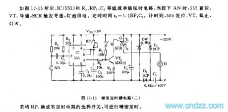
As the figure 17-15 shows, as the figure 17-15 shows, the monostable delay circuit is composed of the IC(555) and R2, RP1, C3.etc, when you press AN, 555 sets, VT1 conductd, the SRC trigger the conduction, and the lamp bulb gets the power. The timing time td=1.1RP1C3. When the time is up, 555 resets, VT1 cuts off, the light turns off.
If we changes the RP1 into the select switch with timing resistance, we can get the accurate timing.
Reprinted Url Of This Article:
http://www.seekic.com/circuit_diagram/Signal_Processing/555_darkroom_timer_circuit_2.html
Print this Page | Comments | Reading(3)

Article Categories
power supply circuit
Amplifier Circuit
Basic Circuit
LED and Light Circuit
Sensor Circuit
Signal Processing
Electrical Equipment Circuit
Control Circuit
Remote Control Circuit
A/D-D/A Converter Circuit
Audio Circuit
Measuring and Test Circuit
Communication Circuit
Computer-Related Circuit
555 Circuit
Automotive Circuit
Repairing Circuit
Code: