
Circuit Diagram
Index 1784
KA2309(toy)wireless remote control receiving control regulation circuit
Published:2011/6/1 9:39:00 Author:Lena | Keyword: wireless, remote control, receiving, regulation


KA2309 is a wireless remote control receiving control regulation single integrated circuit applied to toys etc. Internal circuit consists of receiving amplifier, Miller integrator, RC integrator, buffer and voltage regulator etc.
Technical characteristicWide power supply range, the value is 3-18V.The current is small when at rest, the typical value is 10.5mAFew external elements Seven functions Integrated circuit with turbo circuitRelated type is KA2310
(View)
View full Circuit Diagram | Comments | Reading(2228)
WT-1 9823 Communication Single-Chip Microcomputer Integrated Circuit Diagram
Published:2011/5/20 19:14:00 Author:leo | Keyword: WT-1 9823 Communication Single-Chip Microcomputer Integrated Circuit Diagram

WT-1 9823 is a kind of single-chip microcomputer integrated circuit used for communication which is mainly applied in caller ID display telephone. The main feature of WT-1 9823 is that its integrated circuit contains pulse/dual-tone command circuit, FSK/DTMF caller ID display data processing circuit, clock circuit and input/output port, key switch coder-decoder circuit, silence control circuit, busy signal test circuit and so on. Its pins function and related data are as what is shown in the picture.
(View)
View full Circuit Diagram | Comments | Reading(555)
KA2305A (toy)wireless remote control receiving control regulation circuit
Published:2011/6/1 9:39:00 Author:Lena | Keyword: wireless, remote control, receiving, regulation


KA2305A is a wireless remote control receiving control regulation single integrated circuit applied to toys etc. Internal circuit consists of receiving amplifier, RC integrator, buffer and voltage regulator etc.
Technical characteristicWide power supply range, the value is 3-18V.The current is small when at rest, the typical value is 10.5mAFew external elementsThe circuit has three functions, go ahead, stop and fall back.12-pin SIP-SH package
(View)
View full Circuit Diagram | Comments | Reading(621)
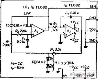
Waveform and Low Distortion SLF Two-phase Oscillation Circuit
Published:2011/6/5 8:06:00 Author:Michel | Keyword: Waveform, Low Distortion, SLF, Two-phase Oscillation Circuit
Circuit's Functions
The phase oscillator which can get SIN and COS waves is often used as AC motor signal generator and can also be used as signal source of orthogonal coordinate transformation and adopted as graphic display of X and Y monitor.This circuit is oscillation stability circuit without AGC loop and it can obtain oscillation output when it is low frequency.
Circuit's Work PrincipleOP amplifier,A1 constitutes level 2 low-pass filter,cutoff frequency's phase lags 90 degree, the amplitude is -3DB and integral circuit has nothing to do with the frequency.But it lags 270 degree,the whole circuit produces 360-degree phase shift. (View)
View full Circuit Diagram | Comments | Reading(710)
KA2304 (toy)wireless remote control receiving control regulation circuit
Published:2011/6/1 9:39:00 Author:Lena | Keyword: wireless, remote control, receiving, regulation


KA2304 is a wireless remote control receiving control regulation single integrated circuit which is applied to toys etc. Internal circuit consists of receiving amplifier, detector, comparator, lock circuit, driver and voltage regulator etc.
Technical characteristicWide power supply range, the value is 2.5~10V.Few external elementsThe circuit has two functions, go ahead and fall back.9-pin SIP package
(View)
View full Circuit Diagram | Comments | Reading(627)
KA2303 (toy)wireless remote control receiving control regulation circuit
Published:2011/6/1 9:40:00 Author:Lena | Keyword: wireless, remote control, receiving, regulation


KA2303 is a wireless remote control receiving control regulation single integrated circuit applied to toys etc. Internal circuit consists of receiving amplifier, detector, comparator, lock circuit, driver and voltage regulator etc.
Technical characteristicWide power supply range, the value is 2.5~10V.The current is small when at rest, the typical value is 5mAFew external elementsThe circuit can drive little direct-current generator and has three functions, go ahead, stop and fall back.9-pin SIP package
(View)
View full Circuit Diagram | Comments | Reading(1170)
TMP47C433AN (TV set) microprocessor
Published:2011/6/6 8:48:00 Author:Lena | Keyword: microprocessor
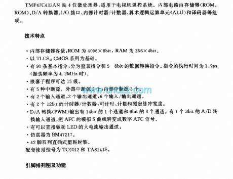
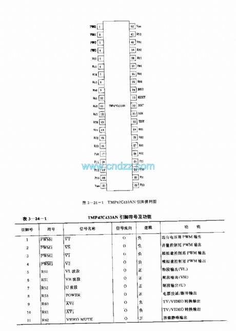
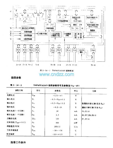

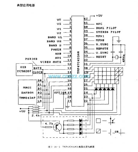
TMP47C433AN is a 4-bit microprocessor applied to TV remote control system. Internal circuit consists of memory(ROM、ROM),D/A converter, I/O interface, internal calculagraph /counter, arithmetic logic unit(ALU) and encoder etc.
Technology characteristicInternal memory capability: ROM is 4096×8bit,RAM is 256×4bit.Based on TLCS47CMOS series.Ninety basic instructions are classified to select table instructions and 5-8bit data convert instructions. Execution time is 1.9μs(oscillation frequency is 4.2MHz).
(View)
View full Circuit Diagram | Comments | Reading(1242)
MAX489/491 low power consumption RF transceiver circuit
Published:2011/5/26 1:15:00 Author:Christina | Keyword: low power consumption, RF transceiver

The MAX489/491 is designed as one kind of low power consumption RF transceiver that can be used in the RS-485 and RS-422 standard communications, it has the short-circuit current limiting function. The driver part's output port is in the high impedance state when it gets into the hot standby state, so it can prevent the overload of load; the receiver part's input port has the safety function to prevent the opening circuit, and it can undertake full-duplex communication. The MAX489/491 uses the conversion rate driver to minimize the electromagnetic interference, and it also has the inhibiting effect to the reflection which is caused by the not appropriate port-connection of the cables, so there is no error when it is transmitting the data in the high speed of 250Kb/s, the driver's highest changing rate can reach 2.5 Mb/s, so it can be used in the industrial automatic control data transmission application.
(View)
View full Circuit Diagram | Comments | Reading(998)
AC Voltage Regulator Twelve
Published:2011/6/3 6:54:00 Author:Michel | Keyword: AC, Voltage Regulator, Twelve

The AC voltage regulator uses servo-type control circuit which has wide voltage regulation range(The input AC voltage range is 160-260V)and high control accuracy.This circuit is easy to make and suitable for where the utility power is unstable.
Circuit's Work Principle
The AC voltage regulator circuit is composed of 士l2V mains circuirt ,voltage test circuit and overvoltage protection circuit and it is showed as the picture 5-51.The 士l2V power supply circuit consists of powerstat,W4 and W5,commutation diode,VD1-VD4 and filter capacitor C1 and C2. (View)
View full Circuit Diagram | Comments | Reading(2394)
AC Voltage Regulator Eleven
Published:2011/6/3 7:47:00 Author:Michel | Keyword: AC, Voltage Regulator, Eleven

This example introduces an AC regulator composed of electronic switching IC and thyristor etc.Comparedwith the AC voltage regulator whose voltage converts by relay,it has no mechnical converting noises and momentary breakdown with long performance life.The regualtor can make sure the output voltage is 220V士l0V when the input AC voltage alters between 160-250V.
Circuit's Wrok Principle
The regulator circuit consists of four groups of stabilized voltage control circuit and it is showed as the picture 5-50.The first group stabilized voltage control circuit is composed of thyristor VT1,VT2,diode VD1,rectifier bridge UR1,resistor R1-R4, potentiometer RP1,capacitor C1,C2,electronic switching Intergrated Circuit IC1,transistor V1 and transformer group's W1 and W2. (View)
View full Circuit Diagram | Comments | Reading(971)
A/D converter 5G14433 and the microprocessor general interface circuit
Published:2011/5/26 7:17:00 Author:Christina | Keyword: A/D, converter, microprocessor, general interface

View full Circuit Diagram | Comments | Reading(542)
Water level indicator circuit (3)
Published:2011/5/29 9:01:00 Author:Christina | Keyword: Water level, indicator

The water level indicator circuit is composed of the three-stage water level indicator circuit and the audio oscillator, as the figure shows.
The three stages water level indicator circuit is composed of the water-level sensor, the transistors Vl-V3, the light-emitting diodes Rl-R9. The low water level (1/3 water level) display circuit is composed of the VLl and Vl, Rl, R3; the 2/3 water level display circuit is composed of the VL2, R4-R6, V2; the high water level display circuit is composed of the VL3 and R7-R9, V3.
The audio oscillator is composed of the transistors V4 and V5, the resistors RlO and RII, the capacitor C.
The VL4 is the power indicator light emitting diode; the BL is the fuu-water alarm speaker.
When the water level of the water tank is lower than the low water level electrode L, the Vl-V3 cut off, the VLl-VL3 turn off. (View)
View full Circuit Diagram | Comments | Reading(1839)
AC Voltage Regulator Ten
Published:2011/5/22 1:25:00 Author:Michel | Keyword: AC Voltage Regulator, Ten

The AC voltage regulator introudced in the example has the features of broad voltage regulation range(102-262V),perfect protection effects(powerdown delay electrification,380V phase dislocation-proofing and lightning protection and statics-proofing etc.) and high sensitivity and it's available in families with unsable line voltage.
Circuit's WorkPrincipleThe AC voltage regulatorcircuit is composed of +5V voltage regulation circuit,voltage test circuit,control circuit,protection circuit and voltage regualation output circuit and it is showed as the picture 5-49.The +5V voltage regulation circuit consists of fuse,FU1-FU3,autotransformer,T,commutation diode,VD1,filter capacitor,C1,three-terminal voltage regulation IC,IC1,resistor,R21 andpowersupply indication LED,VL. (View)
View full Circuit Diagram | Comments | Reading(2334)
AC Voltage Regulator Nine
Published:2011/5/22 1:29:00 Author:Michel | Keyword: AC Voltage Regulator, Nine

The AC voltage regulator introudced in the example is made from 100-200W mains transformer and discrete components with simple circuits and material which can be used by the area's famlies whose line voltage is low(190-220V).
Circuit's Work Principle
The AC voltage regulator is composed of power supply circuit,voltage test control circuit and it is showed as the picture 5-48.The power supply circuitconsists of mains switch,S,fuse,FU,transformer,T,diode,VD2,capacitor,C1-C3,power suorce indication LED,VL2,resistor,R2 and R8 and voltage regulation diode,VS.
(View)
View full Circuit Diagram | Comments | Reading(1207)
△ connection electromotor phase loss voltage relay protection circuit
Published:2011/5/30 1:42:00 Author:Christina | Keyword: △ connection, electromotor, phase loss, voltage relay, protection circuit

The △ connection electromotor phase loss voltage relay protection circuit is as shown:
For the △ connection electromotor, there need to be a artificial neutral point, we use three equivalent capacitance to form the Y-shape to connect with the electromotor in parallel connection, then we add the protection components at the midpoint of this Y-shape, as the figure shows. When the motor three-phase power is normal operation, the neutral voltage U00 is lower than 10V. If the phase is broken when the electromotor load is operating, the neutral voltage U00 is related with the load, the change range is 10 to 50V. IF we use the DJ131/60CN type voltage relay, the action voltage can be setting in 20 ~ 25V; if the electromotor's load is lower than 50% ~ 60%, the setting voltage is 15 ~ 20V. (View)
View full Circuit Diagram | Comments | Reading(1273)
AC Voltage Regulator Eight
Published:2011/5/22 1:13:00 Author:Michel | Keyword: AC Voltage Regulator, Eight

The automatic AC voltage regulatorintroduced in the example owns broad voltage regulation range,which can output 220V alternating voltage when the input alternating voltage is 110-380V so it's availabe for where the alternating voltage power supply is unstable.
Circuit's Work Principle
This AC voltage regulator circuit is composed of power supply circuit,voltage test control circuit and voltage regulation output circuit and it is showed as the picture 5-47.The power supply circuit consists of reduction voltage capacitor,C2,current-limiting resistor,R31and R33,commutation diode,VD44 and VD45,filter capacitor,C3 and C4,potentiometer,RP and voltage regulation diode,VS1. (View)
View full Circuit Diagram | Comments | Reading(1704)
AC Voltage Regulator Seven
Published:2011/5/22 1:10:00 Author:Michel | Keyword: AC Voltage Regulator, Seven

The AC voltage regulator introudced in the example has the functions of bootstrap power transmission delay,regulated output voltage,overvoltage and undertension's protection and indication and its output power is 3kW.
Circuit's Work PrincipleThe AC voltage regulator is composed of power supply circuit,lifting and reduction control circuit,bootstrap time delay circuit,overvoltage protection circuit and undertension protection circuit and it is showed as the picture 5-46.The power supply circuit consists of mains switch,S1, voltmeter,PV1,voltage-regulating transformer,T,rectifier bridge,UR2 and three-terminal voltage regulation IC,IC1,and filter capacitor,C1 and C2. (View)
View full Circuit Diagram | Comments | Reading(2433)
AC Voltage Regulator Six
Published:2011/5/22 1:08:00 Author:Michel | Keyword: AC Voltage Regulator, Six

The voltage AC regulator introduced in the example is controlled by SL322 LED driver IC.It can be used as automatic tap changer and voltage lighting indication where the commercial power often is low.
Circuit's Work Principle
The voltage AC regulator is composed of power supply circuit,voltage test control circuit and control operation circuit and it is showed as the picture 5-45.The power supply circuit consists of fuse,FU ,mains transformer,T,rectifier bridge,UR and filter capacitor,C1. (View)
View full Circuit Diagram | Comments | Reading(2509)
AC Voltage Regulator Five
Published:2011/6/3 5:02:00 Author:Michel | Keyword: AC Voltage Regulator, Five

The input and output voltage of the lifting voltage AC regulator introduced in the example are 150-230V and 220 (1土5%)V respectively.This regulator can be used by these families with unstabilized and low voltage.
Circuit's Work Principle
This AC regulator circuit is composed of power supply circuit,voltage test circuit and lifting voltage control circuit and it is showed as the picture 5-44.The power
supply circuit consists of mains switch,S,fuse,FU,mains transformer,T,commutation diode,VD1-VD4,filter,capacitor,C1 and C2 and three-termianl voltage control IC,IC. (View)
View full Circuit Diagram | Comments | Reading(2108)
AC Voltage Regulator Four
Published:2011/5/22 1:02:00 Author:Michel | Keyword: AC Voltage Regulator, Four

The input and output voltage range and output power range AC voltage regulator introudced in the example are 160-270V,220(1士5%)V and 600-800W respectively,which can meet the need of general household appliances.
Circuit's Work Principle
The AC voltage regulator circuit is composed of lifting and reduction voltage commutation circuits and automatic control circuit and it is showed as the picture 5-43.The lifting and reduction commutation circuits consists of power supply transformer's(T) Wl-W6 winding,relay's normally closed contact Kl-l-K5-1,normally open contact Kl-2-K5-2 and voltmeter,PV and it is showed as the picture. (View)
View full Circuit Diagram | Comments | Reading(4239)
| Pages:1784/2234 At 2017811782178317841785178617871788178917901791179217931794179517961797179817991800Under 20 |
Circuit Categories
power supply circuit
Amplifier Circuit
Basic Circuit
LED and Light Circuit
Sensor Circuit
Signal Processing
Electrical Equipment Circuit
Control Circuit
Remote Control Circuit
A/D-D/A Converter Circuit
Audio Circuit
Measuring and Test Circuit
Communication Circuit
Computer-Related Circuit
555 Circuit
Automotive Circuit
Repairing Circuit