
Circuit Diagram
Index 1790
First-order Active Phase Shift Oscillator Circuit
Published:2011/5/25 4:40:00 Author:Joyce | Keyword: First-order , Active , Phase Shift , Oscillator
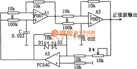
As shown in the figure is the first-order active phase shift oscillator circuit. In this circuit, the first-order active phase shift oscillator is composed of A1 and A2, which forms a loop circuit with A3.A3 is an inverse proportion amplifier, mainly responsible for amplification. The gain control of A3 is -1,and the shift phase is π.D1、D2 are voltage-regulator tubes 2DW7C which will help to stabilize the amplitude. In orderto meet the condition of oscillation, the absolute value of transmission coefficient βof the first-order active phase shift oscillator is 1. When the overall shift phase reaches π,the circuit would start oscillation. The oscillation frequency is:
f0=1/2πRC. (View)
View full Circuit Diagram | Comments | Reading(774)
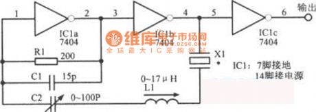
2~20MHz Variable Frequency Transistor Oscillator Circuit
Published:2011/5/29 1:41:00 Author:Joyce | Keyword: 2~20MHz, Variable Frequency , Transistor Oscillator
View full Circuit Diagram | Comments | Reading(701)
Negative Voltage Generated Circuit Composed of Timer IC555
Published:2011/5/25 4:45:00 Author:Joyce | Keyword: Negative Voltage, Generated , Timer IC555

View full Circuit Diagram | Comments | Reading(597)
Simulated Pendulum Circuit Composed of CD4017
Published:2011/6/2 9:58:00 Author:Joyce | Keyword: Simulated, Pendulum , CD4017

Making use of the characteristics of the ten output ends of CD4017 that they will move as being input with clock pulse, it is connected with a luminous diode in each of its output ends. The movement of output position will make the light emitting diode function, thus forming a simulated pendulum circuit. If it is installed in digital electronic clocks, it can not only make the clock work, but it can serve as a kind of adornment. The composition of the circuit is shown in the graph.
(View)
View full Circuit Diagram | Comments | Reading(1245)
the simple phone repairer
Published:2011/6/2 23:16:00 Author:Seven | Keyword: phone repairer

View full Circuit Diagram | Comments | Reading(456)
The high quality stereo power amplifier circuit
Published:2011/6/3 0:06:00 Author:Seven | Keyword: high quality, stereo power amplifier

In Figure 19-22 is a simple circuit which consists of a TDA2310 dual preamplifier integrated circuit and a TDA2004 dual-audio power amplifier. The output power may reach 2*10W, and the supply voltage is 14.4V.
(View)
View full Circuit Diagram | Comments | Reading(1860)
The speed governing fan circuit
Published:2011/6/3 0:15:00 Author:Seven | Keyword: speed governing fan

View full Circuit Diagram | Comments | Reading(524)
the computer fan circuit
Published:2011/6/2 23:13:00 Author:Seven | Keyword: computer fan

View full Circuit Diagram | Comments | Reading(6065)
The completed power amplifier circuit--the Wilson tube amplifier(copy)
Published:2011/6/3 Author:Seven | Keyword: power amplifier, Wilson tube amplifier

View full Circuit Diagram | Comments | Reading(715)
The hotplate circuit
Published:2011/6/2 23:01:00 Author:Seven | Keyword: hotplate circuit

View full Circuit Diagram | Comments | Reading(577)
The phone security device circuit of photocouplers
Published:2011/6/3 0:17:00 Author:Seven | Keyword: security device, photocouplers

View full Circuit Diagram | Comments | Reading(444)
The phone dialing circuit
Published:2011/6/2 23:56:00 Author:Seven | Keyword: dialing circuit

In Figure 11.3 is a key dialing circuit which is made of DF320. When the phone is picked up, the circuit is on. The NPN VT2 is conducting due to the input basic polarity of R2, and VT1 is also conducting, so the power supply charges C2 to 0.7V by R3 and VD1. When the LEV reaches the minimum working voltage of VDD, DF320 is linked to the power supply, and the circuit is reset by C1 and R8. The telephone net is linked to the circuit by VT1, and DF320 net, as an impedance, connects with the phone in the parallel way.
(View)
View full Circuit Diagram | Comments | Reading(514)
The ABS fault detecting circuit of Santana 20OOGSi
Published:2011/5/13 22:10:00 Author:Borg | Keyword: ABS, fault detecting, Santana


ABS computer J104 can not only control wheel brakeing automatically, but also detect its own faults. When it detect something wrong ABS, it will save it as the form of codes and light the ABS alarm lamp to remind the driver to remove it in time. In addition, there are some faults without any codes, which should be handled in regular methods. ABS fault detection can be completed with VAG1552 diagnostic apparatus,Fault codes and the removing methods are in Figure 1, and parameter detection in Figure 7, valve detection in Figure 8.
(View)
View full Circuit Diagram | Comments | Reading(638)
The detection circuit of Santana power control system components
Published:2011/5/14 4:00:00 Author:Borg | Keyword: detection circuit, Santana, power control system


To detect if a component links to computer J220, we can refer to Figure 1 to Figure 6, the part between terminal of 80 connector and connector of sensor or executor is tested with ohm mode(with buzz) of multimeter; generally, if the connection is OK, i.e without disruption or eroding, the displayed number will be less than o.5Ω; even in the long circuit, the resistence is under 1Ω, and the buzzer will buzz if not. Figure 3 the disruption detection between AJR engine power-control ECU system and components
(View)
View full Circuit Diagram | Comments | Reading(702)
CXD750096-013Q- the integrated microcomputer circuit of system control
Published:2011/5/14 21:17:00 Author:Borg | Keyword: integrated microcomputer circuit, system control

1.function featuresCXD750096-013Q contains IC trunk control circuits, key switching encoding circuits, main synchronous signal processing circuits of 100Hz, main/vice tuner AFT signal processing circuits, OSD display circuits,main synchronous signal processing circuits of 50Hz, indicator drive control circuits, audio protection test circuits and silence-noise control circuits, etc.2.pin functions and dataCXD750096-013Q is in flat 64-lead package, whose pin functions and data are listed in Table 1-1.Table 1-1 pin functions and data of CXD750096-013Q
(View)
View full Circuit Diagram | Comments | Reading(2592)
The control circuit of Santana AJR(ZVQS) power jet engine
Published:2011/5/14 10:32:00 Author:Borg | Keyword: control circuit, Santana, power jet engine
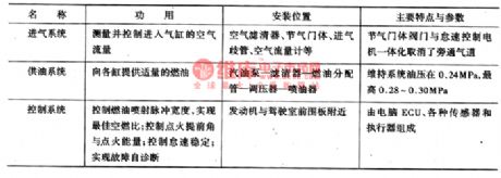
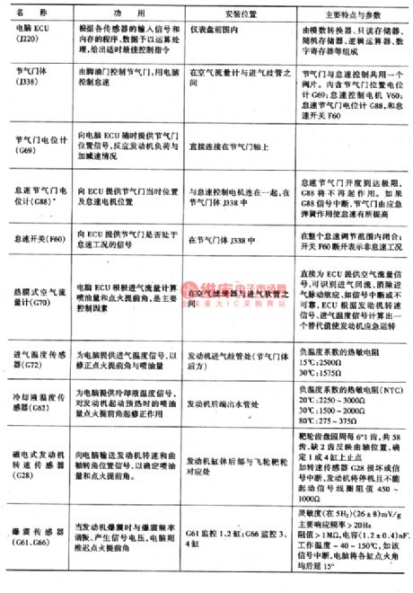


AJR engine is simplified engine without intermediate shafts or electricity distributors, whose igniting order comes from the engine computer(ECU), and ECU delivers the order after getting the signals coming from the engine speed sensor(G28) and camshaft position (Hall) sensor(G40).the construction features of M3.8.2 control systemThe composition, functions, position and features of M3.8.2 power-controlled multiple petrol jet system that is fixed in AJR engine are as shown in Figure 1.Figure 1. The power-controlled petrol jet system of AJR engine
(View)
View full Circuit Diagram | Comments | Reading(571)
BA3519F-the integrated reproducing circuit of single door stereo
Published:2011/5/14 22:17:00 Author:Borg | Keyword: integrated reproducing circuit, single door stereo


BA3519F is an integrated reproducing circuit of single door stereo produced by Toyo Corp., Japan, which is widely used in stereo monoplayers or portable radios.1.the internal circuit and pin functions of BA3519F BA3519F contains dual heads and dual amplifiers. In front of the dual heads, there are electronic switches converting the signals of two sides of cassettes, so the IC is often used in walk-man with the functions of auto reversing, such as Aiwa walk-man and so on.BA3519F is in flat 22-lead dual line package.
(View)
View full Circuit Diagram | Comments | Reading(808)
MC33260 power factor regulating integrated circuit
Published:2011/6/9 0:55:00 Author:Christina | Keyword: power factor, regulating, integrated circuit


The MC33260 is designed as one kind of power factor regulating integrated circuit that is produced by the MOTOROLA company, and it can be used in wide range of applications such as the rear projection color TVs and the LCD color TVs.
1.Features
The MC33260 integrated circuit is composed of the reference voltage and current formation and correction circuit, the over-voltage and undervoltage detection circuit, the oscilation circuit, the current detection comparator, the current converter circuit, the voltage regulating circuit, the PWM comparative circuit, the synchronization tracking circuit, the buffer amplifier and other auxiliary circuit, the internal circuit block diagram is as shown in figure 9.
The internal circuit block diagram of the MC33260
2.Pin functions and data
The MC33260 is in the 8-pin double-row DIP plastic apckage, the pin functions and data is as shown in the table, this data is measured from the ChangHong JingXian rear projection color TV.
The pin functions and data of the MC33260
(View)
View full Circuit Diagram | Comments | Reading(722)
Amplifier tube protector circuit
Published:2011/6/8 6:32:00 Author:Christina | Keyword: Amplifier tube, protector

The amplifier tube protector circuit is as shown in the figure.
Working principle: K is the power supply switch, T1 is the small control power transformer, T2 is the amplifier power transformer. The IC1(S1-S4) is the four-way analog switch CD4066. When the circuit is booting, you need to close K1, so the C1 gets the 12V DC current. At this time the S3 conducts because the control port has the high electrical level, if you make the control port of S4 to have the low electrical level, the S4 will cut off. The voltage of C2 can not be changed, so the S1 conducts because of the control port has the high electrical level, the optocoupler IC2's LED turns on, the photodiode conducts to make the amplifier volume potentiometer's output audio signal shorted to ground. After the S1 is conducted, C3 charges for few tenths second, the S2 conducts, then the VT conduct, the relay J closes to connect the amplifier power supply. (View)
View full Circuit Diagram | Comments | Reading(452)
MC33033 brushless DC motor drive control integrated circuit
Published:2011/6/9 1:07:00 Author:Christina | Keyword: brushless, DC, motor, drive control, integrated circuit


The MC33033 is designed as one kind of brushless DC motor drive control integrated circuit that is produced by the MOTOROLA company, it can be used in the electric bicycle and other occasions that need to drive the brushless DC motor.
1.Features
The MC33033 is composed of the rotor position decoder, the reference voltage regulator, the oscillator, the error amplifier, the pulse width modulation comparator, the current limiting protection circuit, the under voltage locking circuit, the overheat protection circuit and the drive output circuit.etc.
2.Pin functions and data
The MC33033 is in the dual-row 20-pin package, the pin functions and data is as shown in the table.
The pin functions and data of the MC33033
3.The internal circuit block diagram and the typical application circuit
The internal circuit block diagram and the typical application circuit of the MC33033 is as shown.
The internal circuit block diagram and the typical application circuit of the MC33033 (View)
View full Circuit Diagram | Comments | Reading(3419)
| Pages:1790/2234 At 2017811782178317841785178617871788178917901791179217931794179517961797179817991800Under 20 |
Circuit Categories
power supply circuit
Amplifier Circuit
Basic Circuit
LED and Light Circuit
Sensor Circuit
Signal Processing
Electrical Equipment Circuit
Control Circuit
Remote Control Circuit
A/D-D/A Converter Circuit
Audio Circuit
Measuring and Test Circuit
Communication Circuit
Computer-Related Circuit
555 Circuit
Automotive Circuit
Repairing Circuit