Measuring and Test Circuit
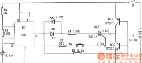
The controllable silicon fast tester circuit
Published:2011/6/6 1:20:00 Author:Seven | Keyword: controllable silicon, fast tester | From:SeekIC

In the figure is the controllable silicon fast tester circuit. The tester consists of pulse signal generator, close-loop conducting circuit, LED and controllable silicon SCR, etc.
The pulse signal generator is a multi-resonate oscillator which consists of the time-based circuit 555, R1, R2 and C, etc, the oscillating frequency is f=1.44/(R1+2R2)C. The oscillating frequency of the parameter in the figure is about 1Hz. As R1<<R2, so the charging time of C is t(charging)=0.693(R1+R2)C, and it is close to the discharging time which is 0.693R2C, so the duty cycle of the output pulse is close to 1:1.
Reprinted Url Of This Article:
http://www.seekic.com/circuit_diagram/Measuring_and_Test_Circuit/The_controllable_silicon_fast_tester_circuit.html
Print this Page | Comments | Reading(3)

Article Categories
power supply circuit
Amplifier Circuit
Basic Circuit
LED and Light Circuit
Sensor Circuit
Signal Processing
Electrical Equipment Circuit
Control Circuit
Remote Control Circuit
A/D-D/A Converter Circuit
Audio Circuit
Measuring and Test Circuit
Communication Circuit
Computer-Related Circuit
555 Circuit
Automotive Circuit
Repairing Circuit
Code: