Measuring and Test Circuit
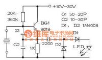
The crystal test circuit
Published:2011/6/5 21:51:00 Author:Seven | Keyword: crystal test | From:SeekIC

With some simple elements, we can make a crystal test circuit which can detect the frequency ranges 10kHz-100MHz, BG1 connects with a multi-resonate oscillator, after being detected by C3,D1 and D2, a voltage of upper-negative and lower-positive is got on the LED, which drives the LED to flow. If the crystal is broken, the LED won't glow. This circuit can be installed in a repairing power supply, leaving 2 holes for crystal detecting elements. Notes for assembling: the two wires led out from the crystal can be too close, or the amplitude will be highly reduced and the LED won't flow.
Reprinted Url Of This Article:
http://www.seekic.com/circuit_diagram/Measuring_and_Test_Circuit/The_crystal_test_circuit.html
Print this Page | Comments | Reading(3)

Article Categories
power supply circuit
Amplifier Circuit
Basic Circuit
LED and Light Circuit
Sensor Circuit
Signal Processing
Electrical Equipment Circuit
Control Circuit
Remote Control Circuit
A/D-D/A Converter Circuit
Audio Circuit
Measuring and Test Circuit
Communication Circuit
Computer-Related Circuit
555 Circuit
Automotive Circuit
Repairing Circuit
Code: