Signal Processing
Home Appliance Timing Blackouts Controller Circuit Composed of 555
Published:2011/6/2 3:35:00 Author:Joyce | Keyword: Home Appliance, Timing , Blackouts , Controller, 555 | From:SeekIC

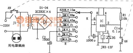
As shown in the figure is an electrical appliances timing blackouts control circuit.it consists of a step-down rectifier circuit, a timing circuit, and a relay control circuit etc among which the step-down rectifier circuit supplys power to the controller.
The timing circuit is a monostable delay circuit composed of IC (555) , R, C and some other components, and the timing time depends on the magnitude of charging and discharging time RC. When one stwiches on AN, 555 will start to set because the potential of feet ② is low level,and the high level output by feet③ will actuate relay J , so contacts J1-1 will be on to put the power through. At this time, timing starts and capacitor C will be charged through R. When the voltage of C is big enough to make the potential of feet⑥ of 555 higher than 2/3VDD, 555 will be reset,the low level output by feet③ will release relay J.so contacts J1-1 will cut off leading to appliance blackouts.The time for home appliance outages time can regulated by using K to choose different gears .
Reprinted Url Of This Article:
http://www.seekic.com/circuit_diagram/Signal_Processing/Home_Appliance_Timing_Blackouts_Controller_Circuit_Composed_of_555.html
Print this Page | Comments | Reading(3)

Article Categories
power supply circuit
Amplifier Circuit
Basic Circuit
LED and Light Circuit
Sensor Circuit
Signal Processing
Electrical Equipment Circuit
Control Circuit
Remote Control Circuit
A/D-D/A Converter Circuit
Audio Circuit
Measuring and Test Circuit
Communication Circuit
Computer-Related Circuit
555 Circuit
Automotive Circuit
Repairing Circuit
Code: