
Circuit Diagram
Index 1548
Improved Inphase Parallel Subtraction Circuit
Published:2011/7/11 2:24:00 Author:Joyce | Keyword: Improved , Inphase, Parallel , Subtraction
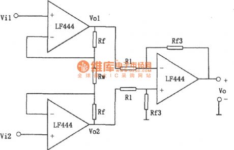
As shown in the figure is an improved inphase parallel subtraction circuit.
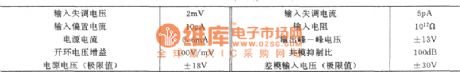
The circuit is not only characteristic of high input resistance, but also overcomes inconveniences caused by Vo which is floating output .Typical values of main parameters of LF444 :
(View)
View full Circuit Diagram | Comments | Reading(563)
Gain Linearity Adjustable Subtraction Circuit
Published:2011/7/11 2:12:00 Author:Joyce | Keyword: Gain, Linearity Adjustable , Subtraction
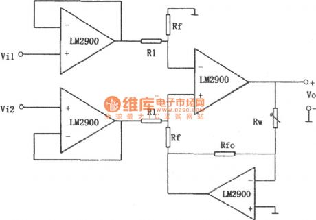
As shown in the figure is a gainlinearity adjustable subtraction circuit.
We can draw from circuit analysis :
Changing the value of Rw can adjust that of the gain, which presents a linear change.
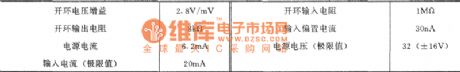
Because the input end of this circuit uses two op-amps as voltage follower, input resistance can be increased greatly. The circuit chooses LM2900 (similar products like CF2900 / CF3900, LM3900) as its component. This series of devices is monolithic integrated current differential four operational amplifier, which is usually referred to as “NORTON amplifier. Its characteristic is that it has a wide range of the power supply, both single and dual powers are feasible, and the output is protected by short circuit.The typical values of the main parameters of LM2900 is as follows:
(View)
View full Circuit Diagram | Comments | Reading(627)
Inphase Parallel Subtraction Circuit
Published:2011/7/11 1:56:00 Author:Joyce | Keyword: Inphase , Parallel , Subtraction
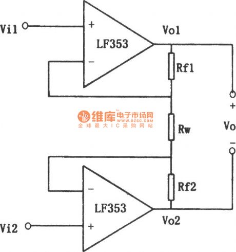

As shown in the figure is an inphase parallel subtraction circuit. The relationship between input and output is shown as follows:
The most obvious characteristic of the circuit is that it has a high input resistance. When the value of Rf1, Rf2 is not 0, changing the value of Rw can adjust the gain quite easily (but it is nonlinear). The external circuit does not need matched resistance. Its defect is that Vo is floating output, which would be inconvenient in some circumstances.
Typical values of the main parameters of LF353: (View)
View full Circuit Diagram | Comments | Reading(564)
Single Power Low Voltage Bandpass Filter Circuit
Published:2011/7/11 2:42:00 Author:Joyce | Keyword: Single Power, Low Voltage, Bandpass , Filter
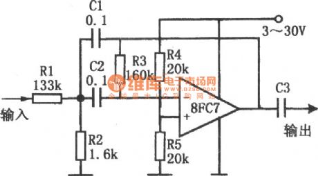

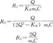
As shown in the figure is a single power low voltage bandpass filter circuit. The circuit uses a single power amplifier 8FC7 to constitute a second-order band-pass filter. Its power supply voltage ranges from 3 V to 30 V. When deciding the value of its component, one needs to identify the center frequency f0 of the band-pass filter, then chooses a suitable capacitance C (C = C1 = C2) according to the following table. After that one should determine the value of Q. which represents a parameter of characteristics of frequency selection. If the value of Q is high, bandpass will be narrow. When Q is 10, one will get a response frequency of - 40 dB every octave. But if the value of Q is too large, the circuit will not be stable. The values of R1, R2, and R3 can be calculated based on the following 3 formulas.
(View)
View full Circuit Diagram | Comments | Reading(596)
Subtraction Circuit
Published:2011/7/11 2:44:00 Author:Joyce | Keyword: Subtraction
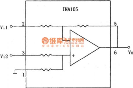
As shown in the figure is a subtraction circuit (1)composed of other components.The relationship of input and output of the circuit is :Vo=10(Vi2-Vi1) (View)
View full Circuit Diagram | Comments | Reading(637)
Active Narrowband Filter Circuit
Published:2011/7/11 3:01:00 Author:Joyce | Keyword: Active , Narrowband , Filter
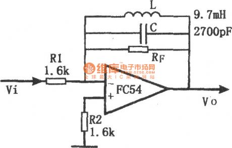

The filter uses LC as feedback impedance of the operational amplifier. The circuit is simple and convenient to debug, and it has the good frequency-selecting performance. Signal gain of the circuit is ZF/R1,and the frequency of the maximum gain point is decided by LC , the amount of which being :
The feedback impedance maximizes and is approximate to RF on the resonance point of LC, so at that time, the circuit has the largest gain. But, it will be influenced by the quality factor of no-load of inductance coil. (View)
View full Circuit Diagram | Comments | Reading(636)
Very Low Frequency Active Filter Circuit
Published:2011/7/11 3:18:00 Author:Joyce | Keyword: Very Low Frequency , Active , Filter
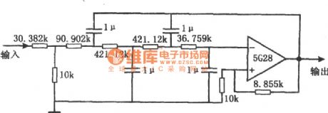
As shown in the figure is a vlf active filter circuit. This is a Butterworth four-order active low-pass filter, which can be used to filter the interference voltage caused by the noise of vlf random pulses on the dc level signal. Its cut-off frequency (-3 dB) is about 8 Hz.When the frequency is 18 Hz, the gain will drop to 20 dB. Natural attenuation within the pass-band is 0.467. And the input resistance is about 40 k Ω. The resistance network of the filter is connected in parallel by several precision resistances with metal film. If the precision of 1μF capacitance reaches a certain amount , the cut-off frequency fc will be close to the theoretical value. (View)
View full Circuit Diagram | Comments | Reading(991)
Power Frequency Noise Filter Circuit
Published:2011/7/14 0:57:00 Author:Joyce | Keyword: Power , Frequency , Noise , Filter

As shown in the figure is a power frequency noise filter circuit. This circuit shows a kind of double T filter, which can filter out noise of 50 Hz (or60 Hz) power frequency when magnifying (such as sensors etc) weak signals . If this sort of filters constitutes of RC components only, the value of Q is generally low, and it will have attenuation characteristics like that of the broadband. Using op-amp and add positive feedback can improve the value of Q. supposing that the value of Q is Q ', then Q '= Q / (1 - K), in which, K = RA / (RA RB). Changing coefficient K would increase the value of Q. The resonance frequency of the circuit fo is 1/2 πRC,and the positive feedback components are R / 2 and 2 C. (View)
View full Circuit Diagram | Comments | Reading(1205)
Circuit of a Filter with 4 Characteristics Simultaneously
Published:2011/7/14 1:12:00 Author:Joyce | Keyword: Filter , Characteristics , Simultaneously
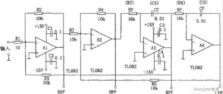
As shown in the figure is a filter circuit with four characteristics at the same time, that is band-pass (BPF), low pass (LPF), high pass (HPF) and elimination (BEF). This circuit is composed of 4 op-amps .The center frequency f0 is decided by RF and CF,as in the formula f0 = 1/2π RFCF.The value of Q in the circuit is decided by R5 / R2 ,and the gain is decided by R2 / R1. R5 = 10 k Ω, therefore when Q = 1,the output for BPF, LPF and HPF is 0 dB. When input is sine wave, output of BEF is 0, and other filters output the same voltage.
(View)
View full Circuit Diagram | Comments | Reading(484)
Automatic Sprinkling Irrigation Controller (8)
Published:2011/7/11 6:31:00 Author:Sue | Keyword: Automatic, Sprinkling Irrigation, Controller
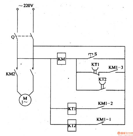
When the power switch Q is on, time relay K will form a circuit by ac contactor KM's normally closed contact KM1-1 and K begins to work. When it reaches Km's given delay time, KT2's time-delay closed normally closed contact will be connected which will make KM connected. KM's normally open main control contact KM2 and two groups of normally open assistant contact KM1-2,KM1-3 will be connected. The water pump electric motor M will begin to work and begin to sprinkle. At the same time, KM's normally closed contact KM1-1 is disconnected which will make Km disconnected. Its normally open contact is disconnected. But because KM's normally open contact KM1-3 has been connected, KM coil remains connected by KT1's time-delay disconnected normally closed contact and KM1-3. M will keep working. (View)
View full Circuit Diagram | Comments | Reading(502)
Automatic Sprinkling Irrigation Controller (6)
Published:2011/7/11 5:58:00 Author:Sue | Keyword: Automatic, Sprinkling Irrigation, Controller
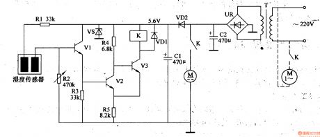
The 220v voltage will generate direct current 6v voltage on the filter capacitor C2 after it is reduced by T. One circuit of the voltage will provide the mini water pump's direct current electric motorwith working voltage(see the dotted line in the figure, the ac electric motor's large and medium water pumps use 220v ac voltage as working power); The other circuit will generate +5.6v voltage which will be provided to V1-V3 and the relay K after it is reduced by VD2, stablized by VS, filtrated by C1.
When the humidity sensor is sticked into the soil, it can detect the soil's humidity. When the soil humidity is high, the resistance value between the humidity sensor's two electrodes is small which will make V1,V2 connected. V3 is disconnected and the relay K is not connected. The water pump motor M doesn't work. When the soil humidity is becoming low, the resistance value between the humidity sensor's two electrode will become higher. When it reaches a certain value, V1 and V2 will be disconnected. V3 is connected and the relay K will be connected. Its normally open contact will be connected which will make the water pump motor M begins to work and the equipment of sprinkler irrigation will begin to work. (View)
View full Circuit Diagram | Comments | Reading(1228)
measuring temperature circuit diagram of TSV type temperature sensor using constant current
Published:2011/7/12 3:45:00 Author:Lena | Keyword: temperature sensor, constant current

In a measuring temperature circuit diagram of TSV type temperature sensor using constant current, when we use constant current as load , the load current will not change,voltage drop of lead wire is a constant,so the ouput voltage will change according to10mV/℃.Usually control distant can reach up to thousand meters.
(View)
View full Circuit Diagram | Comments | Reading(500)
Automatic nickel cadmium battery charger circuit
Published:2011/7/14 2:31:00 Author:TaoXi | Keyword: Automatic, nickel cadmium battery, charger

The circuit is as shown in figure 4-15. The constant current source is composed of the LM7805 and R1. IF you press the switch AN, the power supply voltage will make the relay K2 close; if you loosen the AN, the battery pack GB still supplies the power to the K2, so K2 is also in the closing state, the battery pack discharges through R3, the discharge indicator light LED2 turns on. When the battery pack GB's voltage can not maintain the closing of K2, the circuit will get into the charging state automaticly. When the rechargeable battery voltage increases to the set voltage, the relay K closes to stop charging, the indicator light LED1 turns on, this means the battery is full.
Figure4-15 Automatic nickel cadmium battery charger circuit
(View)
View full Circuit Diagram | Comments | Reading(959)
wireless remote control switch circuit(two)
Published:2011/7/12 7:14:00 Author:Lena | Keyword: wireless, remote control, switch
Here introduces a 4-way wireless remote control switch which adopts wireless remote control transmitting/receiving and wireless remote control coding/decoding integrated circuit, and the switch can control four kinds of different appliance or control different work states of the one applianceat one time.This wireless remote control switch circuit consists of wireless remote control transmitting circuit and wireless remote control receiving circuit, as shown in the figure.The wireless remote control transmitting circuit consists of wireless remote control transmitting head IC1, wireless remote control coder and switch control circuit.
(View)
View full Circuit Diagram | Comments | Reading(1155)
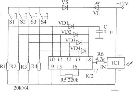
multipurpose wireless remote control switch circuit
Published:2011/7/12 3:38:00 Author:Lena | Keyword: multipurpose, wireless, remote control, switch
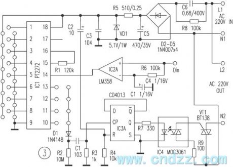
This remote control switch uses wireless code/encode mode, which is not limited by aeolotropy, the beeline control distant is ≤100m.The switch can control electric appliance cut/off whose power is at about 400W.It consists of remote controller and receiving circuit. The remote controller has a small bulk and beautiful shape, and can be hung on a bunch of keys that is convenient to carry-on. The switch has four keystokes which can transmit 4-way control signal respectively.
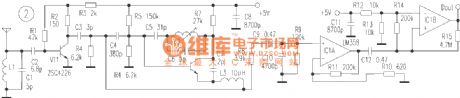
Figure 1 is a remote control emitter circuit.IC1 is a low power loss code transmitting chip using CMOS technology.
(View)
View full Circuit Diagram | Comments | Reading(1231)
infrared remote control electric fan circuit
Published:2011/7/12 3:42:00 Author:Lena | Keyword: infrared, remote control, electric fan


Here introduces a full function infrared remote control electric fan circuit, it has three functions include common wind, nature wind and sleep wind. It controls auto-shake, 0.5~7.5 hours timing off, and has a absolute night twilight spotlight, simple facture and easy usage.
Circuit principle: receiving circuit is shown as figure 1, we can know that the kernel part is a circuit brings togther infrared receiving amplifier, decoding, autocontrol, manual operation, LED emitting diode work state and timing off display set.
(View)
View full Circuit Diagram | Comments | Reading(1834)
wireless remote control code/encode circuit
Published:2011/7/12 7:11:00 Author:Lena | Keyword: wireless, remote control, code/encode

Wireless remote control receiving and transmitting switch circuits are mainly used to transfer data, the purpose is very wide. They are mainly used to centralized control of modern family multi-way power supply, intelligent residential district property management, anti-theft alarm system, wireless water tower control, wireless meter reading, navigation, aeromodelling and remote control measure etc multi-situation. Modern wireless remote control receiving and transmitting switch circuits have advanced circuits, and the manufacture technics have been transited to surface patch technics, integration and modularization from miscellaneous devices. This brings a small bulk, and the effect distant is from meters to few kilometers.
(View)
View full Circuit Diagram | Comments | Reading(496)
Over-Voltage Protection Circuit Composed Of MC3X164 Series
Published:2011/7/13 8:01:00 Author:Robert | Keyword: Over-Voltage, Protection
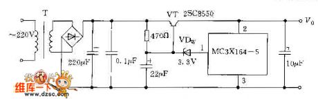
The picture shows the over-voltage protection circuit composed of MC3X164 series. (View)
View full Circuit Diagram | Comments | Reading(585)
TDA4863A Circuit
Published:2011/7/13 7:53:00 Author:Robert | Keyword: Circuit

The picture shows the TDA4863A circuit.
This circuit is used in the Chuangwei 3P30, 4P30 etc. cassette mechanism with main function of field excitation, field output.
Maintenance points: (1)Theflyback lines above the picture can be used to check if the C325's capacity is lower or not. (2)For field center offset it would check if the pin 6 and pin 7's input port voltage are equal. (View)
View full Circuit Diagram | Comments | Reading(4408)
wireless remote control/touch switch circuit
Published:2011/7/12 7:01:00 Author:Lena | Keyword: wireless, remote control, touch switch

This remote control switch circuit can be used as far distance wireless remote control operation, can also control touch in near distance, the usage is very convenient. Composition principle is shown as the figure, it mainly composed by wireless remote control receiving component, touch control circuit, bistable states switch control circuit and power supply circuit. Remote control transmitting circuit uses finished product component TWH9236 which is not shown in figure.
(View)
View full Circuit Diagram | Comments | Reading(1098)
| Pages:1548/2234 At 2015411542154315441545154615471548154915501551155215531554155515561557155815591560Under 20 |
Circuit Categories
power supply circuit
Amplifier Circuit
Basic Circuit
LED and Light Circuit
Sensor Circuit
Signal Processing
Electrical Equipment Circuit
Control Circuit
Remote Control Circuit
A/D-D/A Converter Circuit
Audio Circuit
Measuring and Test Circuit
Communication Circuit
Computer-Related Circuit
555 Circuit
Automotive Circuit
Repairing Circuit