
Circuit Diagram
Index 1542
COP880C--the communication single chip microcomputer integrated circuit
Published:2011/7/12 22:16:00 Author:Borg | Keyword: communication single chip, microcomputer


COP880C is the communication single chip microcomputer integrated circuit, which is often used in the multi-channel wireless phones.1.function featuresCOP880C contains pulse/dual audio with dialing circuit, wireless emitting and receiveing signal process control circuit, channel manual or auto switching circuit, fast auto receiving lines selecting circuit, keypad switch signal encoding circuit, power supply detection circuit, charge detection circuit, mute control circuit, ringing detection circuit, audio channel circuit (for communication) and other function circuits.
(View)
View full Circuit Diagram | Comments | Reading(692)
KA22131-Single chip stereo player integrated circuit
Published:2011/7/13 4:39:00 Author:leo | Keyword: Single chip, stereo player


KA22131 is single chip stereo player integrated circuit produced by Samsung in Korea which is used in the low voltage stereo system. 1.KA22134 inner circuit diagram and pin functions:KA2214 contains two fronted balance amplifiers, power amplifier and cassette type selecting circuit and others. It uses 24-pin dual line flat package and the inner circuit diagram is shown in the picture 1-1.2.KA22134 main parameters:Its work voltage converge is from 1.8 V to 3.6 V and the classic work voltage is 3 V. When Vcc is 3 V and RL is 16 ohms, the Po is 69mW x 2.
(View)
View full Circuit Diagram | Comments | Reading(1563)
The temperature control switch circuit of Nanjing Iveco light car
Published:2011/7/12 7:59:00 Author:Borg | Keyword: temperature control, light car

(17)The temperature control switch of the cooling fan (see as figure 19)
(View)
View full Circuit Diagram | Comments | Reading(507)
The indicator and alarm lamp connection circuit of Santana 2000 (gasoline injection engine)
Published:2011/7/12 20:49:00 Author:Borg | Keyword: alarm lamp, Santana 2000
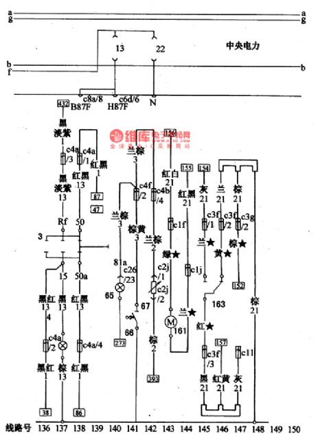
The indicator and alarm lamp connection circuit of Santana 2000 (gasoline injection engine)
The indicator and alarm lamp connection circuit of Santana 2000 (gasoline injection engine)3-starting linked lock switch; 4-gear position indicator; 65-pulling over brake and brake fluid lacking warning lamp; 66-pulling over brake linked switch; 67-brake fluid level control switch; 161-rear shell interlock motor; 163-door shutting micro switch (View)
View full Circuit Diagram | Comments | Reading(449)
The central control door lock and rear window defroster connection circuit of Santana 2000
Published:2011/7/12 20:42:00 Author:Borg | Keyword: central control, door lock, Santana 2000
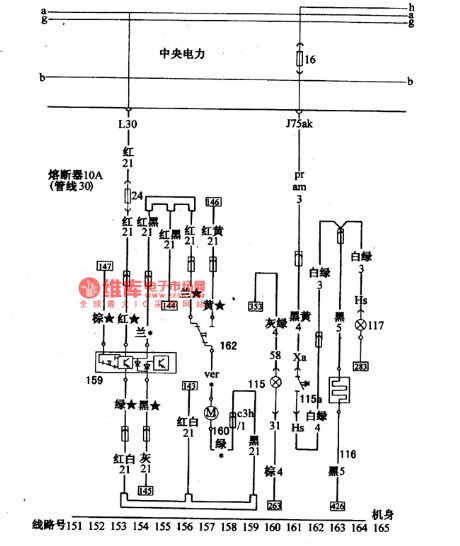
Figure: The central control door lock and rear window defroster connection circuit of Santana 2000 (gasoline injection engine)159-central interlock equipment; 160-right door interlock motor; 162-right door shutting micro switch; 115-rear window defroster switch lighting lamp; 115a-rear window defroster switch; 116-rear window defroster; 117-defroster indicator (View)
View full Circuit Diagram | Comments | Reading(881)
The circuit diagram of a power MOSFET amplifier circuit with high frequency feature
Published:2011/7/13 19:49:00 Author:leo | Keyword: Power MOSFET amplifier, high frequency

The picture 1 is a power MOSFET amplifier circuit with high frequency feature. In order to restrain the influence of the changes of power supply, it takes VT1 and VT2 to form the constant current circuit,while, VT3 and VT4 are end power amplifying circuit. Due to the influence of offset current, its drain currenthastemperature factors which is from positive to negative. Therefore, it uses RP2 to control the offset in order to set the drain current to 0.1 to 0.2 A, which passes through VT3 and VT4. And when its frequency is 1Hz to 800 kHz, the distortion is 0.04% per 1 kHz. At the same time, its output power is 40 W and the convert rate is 100V/μs. (View)
View full Circuit Diagram | Comments | Reading(2465)
KA2292-the single chip stereo radio integrated circuit
Published:2011/7/12 7:38:00 Author:Borg | Keyword: single chip, stereo radio


1. Main functions of KA2292 The FM part of KA2292 includes circuits of FM high-frequency amplifier, local machine oscillating FM mix, FM INTREQ, modulation orthographic discrimination, FM tuning indicator, audio amplifier and so on. The AM part of KA2292 includes circuits of high frequency amplifier, local oscillation, AM mix, AM INTREQ, AM detection, AGC producing, AM tuning indicator and audio amplifier, etc. The stereo sound decoding part of KA2292 includes circuits of PLL amplifier, phase comparing and so on.
(View)
View full Circuit Diagram | Comments | Reading(1537)
The tech parameter circuit of Nanjing Iveco light car
Published:2011/7/12 7:26:00 Author:Borg | Keyword: tech parameter, light car
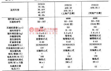
2. The application method of the air-conditioning system(1) cooling by force Fix the cooling switch at the forced state(HAND position), the power supply/wind volume switches are at the Ⅰ,Ⅱand Ⅲ gear respectively, the wind in the car can be regulated. The cooling degree is not controlled by temperature.(2) temperature control cooling Pull the cooling switch to the AUTO gear, then adjust the temperature potentiometer of the temperature controller(WKQ) to the state of setting temperature , finally, choose the wind switch gear to decide the wind volume in the car. The cooling degree is controlled by the WKQ.
(View)
View full Circuit Diagram | Comments | Reading(394)
The air-conditioning system and dashboard circuit of Nanjing Iveco light car
Published:2011/7/12 7:57:00 Author:Borg | Keyword: air-conditioning system, dashboard circuit, light car

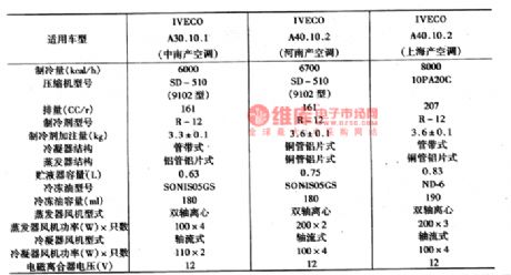
5. The air-conditioning control circuit of Nanjing Iveco light car Nanjing Iveco light cars have many types, and their air-conditioning systems are different (see as the above table), so the control circuit are not the same, here is to introduce them briefly. (1) the air-conditioning circuits of Nanjing Iveco light cars of 30.10V, 40.10V and 40.10VsSee as figure 21, the power source of the control circuit is from the terminal G9 in the central connection box(Gg is connected with igniting switch 15A), the main circuit is from the 30A fuse. The working course of the wind volume switch SA is as follows:
(View)
View full Circuit Diagram | Comments | Reading(565)
CVD-1--the decoding integrated circuit of SVCD player
Published:2011/7/12 3:57:00 Author:Borg | Keyword: decoding, integrated circuit, SVCD player
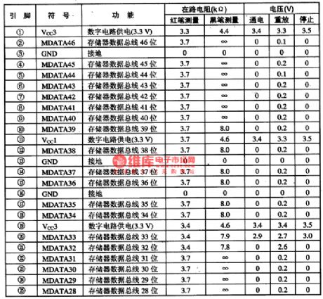
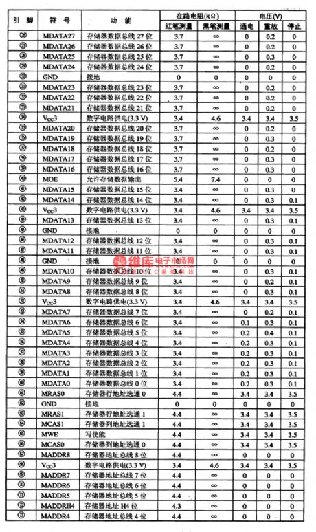
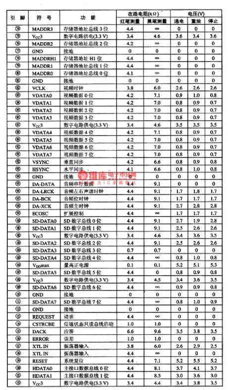
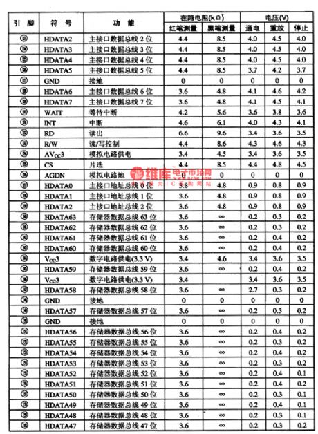
CVD-1 is the decoding integrated circuit of SVCD player, which is used in Changhong and other SVCD players as the decoding circuit.1.function featuresCVD-1 contains the memory, controller, main drive logic control, programme spreading decoder, OSD decoding, layer decoding, MPEG video decoder, MPEG audio decoder, video mixer, synchronized generator, digital audio connector and other circuit unit.2.pin functions and dataCVD-1 is in 160-pin square package structure, whose pin functions and data are listed in table 1.
(View)
View full Circuit Diagram | Comments | Reading(501)
The circuit diagram of a high frequency bias magnetic amplifier used by earphones
Published:2011/7/13 19:50:00 Author:leo | Keyword: Bias magnetic amplifier, high frequency

The picture 1 shows a high frequency bias magnetic amplifier used by earphones. Its resistance is 30 to 100 Ω, so it takes TC28 as the driver to meet the need, whose resistance is 6Ω. In TC28, four simple negaterG1 to G4 make up of a full bridge circuit. This bridge circuit is used to drive the left and right audio channel of the earphones. TL451 is the integrated controller of switch power resourcing. During simulating, if the left and right audio channels output signals with different frequency, the frequency difference will be added to output signals as the deadbeat signals. (View)
View full Circuit Diagram | Comments | Reading(941)
The general switch and off-loading relay connection circuit of Santana 2000(gasoline injection engine)
Published:2011/7/12 20:26:00 Author:Borg | Keyword: general switch, off-loading relay, gasoline injection engine
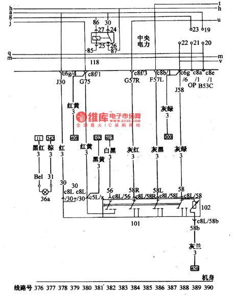
Figure: The general switch and off-loading relay connection circuit of Santana 2000(gasoline injection engine)36-light switch lamp; 101-light general switch; 102-instrument lamp regulating resistor; 118-off-loading relay (igniting switch X cylinder control) (View)
View full Circuit Diagram | Comments | Reading(509)
Cycle timer with open and stop preset function circuit diagram
Published:2011/6/29 4:14:00 Author:Rebekka | Keyword: Cycle timer, preset function

This circuit is a cycle timing controller composed of 555 time base circuit. The time base signals outputed by 555 circuit passes the frequency demultiplication of the digital circuits and gets multi-stage timing control output. It passes the cooperation of the relay, and forms the preset boot, preset shutdown automatic cycle time controller. Its circuit is shown in figure. (View)
View full Circuit Diagram | Comments | Reading(1762)
A differential test circuit made by analog switch
Published:2011/7/13 19:55:00 Author:leo | Keyword: Test circuit, Analog switch

What the picture shows is a differential test circuit made by analog switch. In the circuit, sensor uses hall component H. When magnetic field is imposed vertically on hall component H, the control current value between a and b is l1, then the hall voltage produced is KBI1 plus UB. In this formula UH=KBI1+UB, k is the proportionality constant, UB is unbalanced voltage. In order to clear this unbalanced voltage, we can make the average of the control current I1 of this hall component equal to zero. We can do this by using switch s10 and s20 to convert the control current I1 alternately to make the amplitude of vibration equal to the time at the moment. At the same time, to make the hall component have a steady sensibility, we only need to make the control current I1 steady. Control current is decided by Ur and Rs, that is I1=Ur/Rs. (View)
View full Circuit Diagram | Comments | Reading(742)
Beijing Cherokee wire cross-section conventional and regular circuit diagram
Published:2011/5/6 4:07:00 Author:Rebekka | Keyword: Beijing Cherokee wire, cross-section conventional and regular
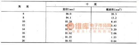
Specify the wire cross-sectional area and color. Figure shows 31-8 Power Configuration in the left side of the first line labeled 12 Red , 12 Orange , where red and orange color shows the wire. 12 is a cross-sectional area wire regular code, the main wiring conventional and regular are shown in figure1. (View)
View full Circuit Diagram | Comments | Reading(376)
Toyota Land Cruiser 70 light off-road vehicle power starting horn rearview mirror principle circuit diagram
Published:2011/5/9 3:15:00 Author:Rebekka | Keyword: Toyota Land Cruiser 70, light off-road vehicle power

l ofbattery; 2 fusible switch line fire switch; 4 start relay; 5 starter; 6 cold start nozzle; 7 the nozzle cold start timer switch; 8 speaker; 9 horn button; 10 remote control mirror switch; 11 left rear view mirror motor; 12 right-rear view mirror; 175 winch main relay; 76 bulb check relay; 37 heat timer; 55 air-conditioning (WC) amplifier; 151 turning and hazard warning switch; F21 ACC ignition switch forconnection from the client. (View)
View full Circuit Diagram | Comments | Reading(1751)
Toyota Land Cruiser 70 light off-road vehicle auxiliary instrument principle circuit diagram
Published:2011/5/9 3:20:00 Author:Rebekka | Keyword: Toyota Land Cruiser 70, light off-road vehicle
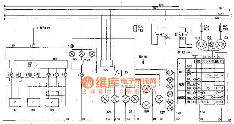
Toyota Land Cruiser 70 light off-road vehicle auxiliary instrument principle circuit diagram.
115 auxiliary instrument panel; 116 digital thermometer; 117 temperature sensor; 118 room temperature sensor 1; 119 room temperature sensor 2; 120 auxiliary instrument panel lighting; 121 auxiliary instrument panel light switch; 122 test plugs; 123 front fog lamp switch; 124 front left and right fog lamps; 125 wide front headlights; 126 taillight; 127 license plate light; 128 instrument lights; 129 taillight relay; headlamp relay; 131 left headlight; 132 light beam; 133 right headlight; 134 light control switch; F2l connection from the ignition ACC fuse switch; 172 headlamp beam control switch; 178digital electric clock; (View)
View full Circuit Diagram | Comments | Reading(1668)
Toyota Land Cruiser 70 light off-road vehicle headlamp beam adjustment winches and clock circuit diagram
Published:2011/5/8 12:36:00 Author:Rebekka | Keyword: Toyota Land Cruiser 70 , light off-road vehicle, headlamp beam adjustment
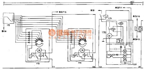
Toyota Land Cruiser 70 light off-road vehicle headlamp beam adjustment winches and clock circuit diagram.
172 headlamp beam control switch; 173 left headlight beam control actuators; 174 right-headlight beam control actuators; 175 winch main relay; 176 winch solenoid switch and motor; 177 winch control switch; 178 digital electric clock; 134 light control switch; F13 taillight relay; 129 battery; F11 IG1 fuse column connected by the ignition switch ; F16 connection from the battery positive 30C line fuse; F13 129 fuse connects from the taillight relay. (View)
View full Circuit Diagram | Comments | Reading(1659)
Mitsubishi Pajero light off-road vehicle circuit instrument panel wiring harness configuration circuit diagram
Published:2011/5/9 2:49:00 Author:Rebekka | Keyword: Mitsubishi Pajero , Light off-road vehicle

01 fuse group; 02 speaker (left); 04 large rear door lock switch; 05 heostat; 06 rear defroster switch box; 08,09 comprehensive instrument; 11 rear wiper and washer switch; 12,13 oil pressure gauge; 14 integrated instrument lighting; 15 the integrated instrumentation and wiring; 16 integrated instrument lighting; 17,18 voltage meter; 19 heating relay; 20,21 empty wither machine wiring A and the former wiring; 22 speaker (right); 23 dedicated fuse; 24 hood and front wiring; 25 hood wiring connection; 27 heating wiring; 28 front door and front wiring; 29 heating fan motor; 30,31 thermal switch; 32 power relay B; 33 air conditioning electromechanical road; 34 power relay A; 35 air conditioner switch; 36 minute; 37 heating fan switch; 38 ashtray light; 39 spare cable connector; 41 parking brake switch; 44 heating control lighting; 46 lights that smoke detectors; 47 meter wiring wiring wiring wiring and the former; 48 heating fan switch; 50,51 light switch; 52 the fire switch; 53 stop light switch; 54,55 withfront door cable wiring and wiring connections before; 56 flash device; 57 power window relay; 58 wiper relay; 59 headlight washer relay; 64 radio; 65 tape recorder; 66 air conditioner cable wiring and wiring connections; 68,69 wiper. (View)
View full Circuit Diagram | Comments | Reading(8344)
KA5L0380——the switch power supply integrated circuit
Published:2011/7/13 11:34:00 Author:Borg | Keyword: switch power supply, integrated circuit


KA5L0380R is a single chip switch power supply integrated circuit of current mode, which is used in DVD players.1.the internal circuitKA5L0380R contains crystal clock circuit, power clamp sampling gating circuit, 5V regulated circuit, internal bias circuit, logic circuit, current limit circuit, over-voltage/current/heat and low voltage protection circuit, whose internal circuit is shown in figure 1-1.
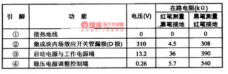
2.pin functions and dataKA5L0380R is packaged in two ways, on of them is 4-pin TO-220F type.
(View)
View full Circuit Diagram | Comments | Reading(4186)
| Pages:1542/2234 At 2015411542154315441545154615471548154915501551155215531554155515561557155815591560Under 20 |
Circuit Categories
power supply circuit
Amplifier Circuit
Basic Circuit
LED and Light Circuit
Sensor Circuit
Signal Processing
Electrical Equipment Circuit
Control Circuit
Remote Control Circuit
A/D-D/A Converter Circuit
Audio Circuit
Measuring and Test Circuit
Communication Circuit
Computer-Related Circuit
555 Circuit
Automotive Circuit
Repairing Circuit