
Circuit Diagram
Index 1543
KA431--the precise reference regulated integrated circuit
Published:2011/7/13 19:52:00 Author:Borg | Keyword: precise reference, integrated circuit

KA431 is a precise reference regulated integrated circuit produced by Samsung, which is widely used in the switch power supply circuit of the color TV, stereo, air-conditioner, disc player and other electric appliances.1.function featuresKA431 contains the sampling fault amplifier circuit, control circuit and other additional circuits.2.pin functions and dataKA431 is in the 3-pin in-line package, whose pin functions and data are listed in table 1-1, and all the data are from the tests on Haier BGBTV-29FA, 29TA, 29F18 and so on.
(View)
View full Circuit Diagram | Comments | Reading(801)
The turning signal, danger signal and internal light (ceiling lamp) circuits of Nanjing Iveco light car
Published:2011/7/12 22:46:00 Author:Borg | Keyword: turning signal, danger signal, internal light, light car
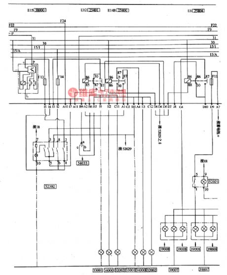
(7) turning signal and danger alarm signal(see as figure 7)The turning lamp switch 54033 (in the grouped switch) is powered by the turning flash relay E15(58000), and left head turning lamp 32002, left side turning lamp 33001, left rear turning lamp 34000(in the grouped lamps) are installed at the side of the turning lamp switch , and the 3 corresponding lamps on the right are installed at other side of the turning lamp, whose part numbers are the same with the ones of the left side. Danger alarm lamp switch 52302 and the turning lamp switch are in parallel connection, and their input powers are also from the flasher E15(58000), the output currents can also be delivered to the left and right turning lamps.
(View)
View full Circuit Diagram | Comments | Reading(454)
Mitsubishi Pajero sport utility vehicle circuit cambodia hood off-line configuration circuit diagram
Published:2011/5/9 2:34:00 Author:Rebekka | Keyword: Mitsubishi Pajero, sport utility vehicle

01 main fusible line; 02,03 fusible wire; 04,054 wheel drive light switch; 06,07 reversing lights and four lights and cords for wiring processing unit integrated; 08,09 backup light switch; l0 air conditioners; 11windshield wiper motor; 14 former wire processing. Reversing lights and the four fixed light wiring processing; 15,16 special fusible wire (power windows circuit); 17 former air conditioner wiring wiring to deal with comprehensive treatment C; 18 forheadlight washer ; 20 light switch relay; 21 front combination lamp (left); 22 dedicated fuse (high beam circuit); 23 headlamp (left); 24,25,26,27 speaker; 28,29.30 little fire coil; 31 fuel cut off solenoid valve; 32 magnetic clutch; 33 , 34 AC generator; 35 oil pressure gauge oil pressure switch devices; 36,37 low-voltage switching; 38 ofheadlamp (right); 39 former air conditioner wiring wiring to deal with treatment B synthesis; 40 the combination of switch (right); 45 front washer motor; 47,48 starter; 49 water temperature sensor; 50 forwater temperature switch; 71 power relay; 72 condenser fan motor. (View)
View full Circuit Diagram | Comments | Reading(3053)
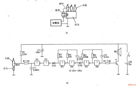
gas flame extinguishment alarm(II)
Published:2011/7/14 20:51:00 Author:chopper | Keyword: gas extinguishment

This example describes the gas flame extinguishment alarm,it can monitor the gas stoves,gas heaters and other gas instruments that use gas.And once gas flame accidentally goes out,the alarm will immediately send an alarm to alert the user to process. Principle of the circuit The gas flame extinguishment alarm circuit includes the flame monitoring control circuit and sound alarm circuit,which is shown in figure 6-205.
(View)
View full Circuit Diagram | Comments | Reading(822)
gas flame extinguishment alarm(I)
Published:2011/7/14 20:51:00 Author:chopper | Keyword: gas extinguishment
This example describes the gas flame extinguishmentalarm, and it can send a alarm when the gas flame turns off accidentlly,and notice the users,in order to eliminate hidden security trouble. Principle of the circuitThe gas flame extinguishment alarm circuit includes flame detection circuit,amplification shaping circuit,2Hz ultra-low-frequency oscillator,lkHz pulse oscillator and audio amplifier output circuit, just as 6-204 shows.
(View)
View full Circuit Diagram | Comments | Reading(3447)
The ceiling lamp, internal lamp, warm air and signal circuit of Nanjing Iveco light car
Published:2011/7/12 21:57:00 Author:Borg | Keyword: ceiling lamp, Nanjing Iveco, light car
(8) wiper, washer, cigarette and radio (see as figure 9)Water jet gear is controlled by key 54033, the current comes from F20, at the same time, the relay circuit and wash pump are powered by it, after the water spray, as the capacitor can release power slowly in some time, which makes the relay contactor pull in for some time, the action of wiping is done for times and the water marks (see as figure 9).The current of the radio and cigarette is from F18 of wire 30, and it comes out from the L plug of the central connection box (L2 terminal).
(View)
View full Circuit Diagram | Comments | Reading(401)
A simple transistor test circuit
Published:2011/7/13 19:55:00 Author:leo | Keyword: Simple transistor test circuit, P channel FET

As the picture a and b show, it is a simple transistor test circuit. The picture13(a) shows a FET test circuit. This circuit is mainly used to test FET pinch-off voltage UP and grid-source voltage UGS. In the circuit, VT is the FET to be tested, and A1 can form servo circuit whose output controls reversal phase input terminal potential and makes it become zero. Voltage-stabilizing diode VD3 and VD4 can produce voltage of±9V and clamp-on the grid potential of VT. R5 is the current limiting resistance which controls VT grid potential current and makes it under the set value. When S2 is connected to 1, VT grid potential voltage is higher than clamp-on voltage and A1 output is negative to the N channel FET while positive to the P channel FET. (View)
View full Circuit Diagram | Comments | Reading(1310)
infant quilt-kicking,bed-wetting alarm
Published:2011/7/14 20:49:00 Author:chopper | Keyword: quilt-kicking, bed-wetting

This example describes the infant quilt-kicking,bed-wetting alarm,which can send the heat preservation caution when the infant kicks the quilt;and it can send the pay attention to changing diapers alarm when infant wets the bed,and it is suitable for home and nursery. The principle of circuitThe infant quilt-kicking,bed-wetting alarm circuit is formed by temperature detection control circuit,bed-wetting detection circuit and alarm circuit,which is shown in figure 6-190. Temperature detection control circuit is formed by the thermistor RT,resistors Rl,R2,potentiometer RP and time-base integrated circuit IC1.
(View)
View full Circuit Diagram | Comments | Reading(1482)
ULN3839A-An AM single chip audio integrated circuit
Published:2011/7/13 19:56:00 Author:leo | Keyword: Single chip audio integrated circuit, Pocket-sized radio

ULN3839A is a kind of single chip audio integrated circuit used in pocket-sized radio and other kinds of radios.
1.ULN3839A integrated chip inner circuit diagram and pin functions:ULN3814A has three suffix: ULN3839A-1, ULN3839A-2 and ULN3839A-3. These three kinds of circuit are almost the same. ULN3839A has all AM audio circuits including AM AGC, LO, MIX, ZF, detection and so on. It adopts 16 pins direct inserting package which you can see in the picture.
2.Main parameters of ULN3839A:Its power supply voltage is 1.8 V to 10 V and the classic operating voltage is 3 V , 4.5 V and 6 V. When Vcc is 3 V and Ta is 25℃, it has the following parameters:(1)Sensibility S. When Vo is 20 mV , its classic value is 3μV(2)Detection output. Its classic value is 100 mV.(3)Voltage gainG(V). Its minimum value is 36 dB and maximum value is 44 dB and classic value is 40 dB.(4)Output power Po. When D is 10%,When Vcc is 3 V, its classic value is 50 mW;When Vcc is 6 V, its minimum value is 250 mW and classic value is 350 mW. (View)
View full Circuit Diagram | Comments | Reading(1302)
infant quilt-kicking alarm(2)
Published:2011/7/14 20:49:00 Author:chopper | Keyword: quilt-kicking
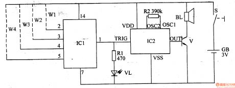
This example describes the infant quilt-kicking alarm,which is mainly formed by the non-door digital IC and music integrated circuit. It can monitor the quilt situation,and senda acoustic and optical alarm signal in time to inform parents when the baby kicks quilt.
The principle of circuit
This infant quilt-kicking alarm circuit is formed by monitor circuit and sound and light alarm circuit, which is shown in figure 6-189.
(View)
View full Circuit Diagram | Comments | Reading(488)
agricultural non-tower pressure-charged water feeder (4)
Published:2011/7/14 20:49:00 Author:chopper | Keyword: non-tower, pressure-charged

The principle of circuit This agricultural non-tower pressure-charged water feeder circuit is formed by power supply circuit and pressure measurement control circuit, as shown in figure 4-155. Power supply circuit is formed by the fuse FU2,knife switch Q2,the power transformer T,the rectifier diode VD and filter capacitor C. Pressure measurement control circuit is formed by the electric connecting pressure gauge Q3,relays K1,K2,intermediate relays M1,KA2,AC contactor KM,thermal relay KR,control buttons S1,S2,and knife switch Q1.
(View)
View full Circuit Diagram | Comments | Reading(549)
agricultural non-tower pressure-charged water feeder(3)
Published:2011/7/14 20:49:00 Author:chopper | Keyword: non-tower, pressure-charged

The principle of circuit This agricultural non-tower pressure-charged water feeder circuit is formed by the power supply circuit, pressure detection circuit,control circuit and indication circuit, which is shown in figure 4-154. Power supply circuit is formed by the knife switch Q1,fuses FU1,FU2 power transformer T,bridge rectifier UR and filter capacitor C. Detection circuit is formed by the electric connecting pressure gauge Q2,resistors R4-R7,normal closed contact K3 of relay K and the transistor V.
(View)
View full Circuit Diagram | Comments | Reading(736)
ZIVA D6 MPEG-2 decoding intergrated circuit diagram
Published:2011/7/13 19:39:00 Author:leo | Keyword: Decoding intergrated circuit, MPEG-2/2 audio

(View)
View full Circuit Diagram | Comments | Reading(234)
The connection circuit of Santana 2000 (gasoline injection engine)
Published:2011/7/12 21:17:00 Author:Borg | Keyword: connection circuit, Santana 2000
Figure: the fuel alarm lamp, air-conditioning fan and fuel pump connection circuit of Santana 2000 (gasoline injection engine)62-gas pressure alarm lamp switch; 61-gas pressure alarm lamp; 140-cooling fanⅡ; 141-cooling heat switch; 142-cooling fan; 134-fan delay switch; 135-cooling fan relay; 45-temperature sensor; 5-gasoline box pump; 5a-cold starting temperature switch. (View)
View full Circuit Diagram | Comments | Reading(350)
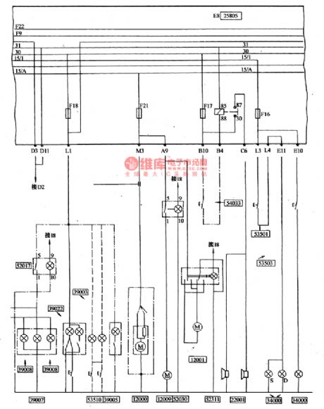
The generator attachment circuit of the Nanjing Iveco light car
Published:2011/7/12 22:49:00 Author:Borg | Keyword: generator attachment, light car
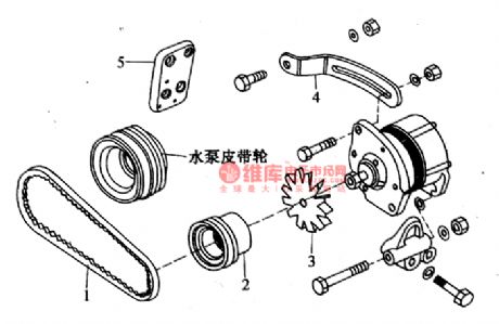
The generator attachmentdiagram of the Nanjing Iveco light car(see as figure 12).
(View)
View full Circuit Diagram | Comments | Reading(370)
CMOO2lAF--the concentrating adjustment control integrated circuit
Published:2011/7/13 19:45:00 Author:Borg | Keyword: concentrating adjustment, integrated circuit
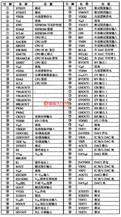
1.function featuresCMOO2lAF contains all types of waveform generators, dynamic concentration and sawtooth generating D/A converter, digital signal process circuit, I and C general connector, transverse/longitudinal control circuit, PWN waveform and clock control circuit for coarse-tuning and fine-tuning. It characterizes high precision(16-bit), high adjusting speed, auto regulation, support of many scanning formats(line frequency range:15.5KHz~48KHz) and so on.2.pin functions CMOO2lAF is in 100-pin QFP plastic package, whose pin functions are listed in table 1.
(View)
View full Circuit Diagram | Comments | Reading(436)
The connector circuit of Santana 2000 whole wires
Published:2011/7/12 21:40:00 Author:Borg | Keyword: connector circuit, Santana 2000
1-igniting pulse signal input 2-shield wire ground connection; 3- normally open contactor of throttle position sensor; 4-igniting switch 50 cylinder connection; 5-ground; 6-shorts; 7-air volume meter signal voltage; 8-admission temperature sensing signal; 9-fuel pump working signal voltage input terminal; 12-Ⅰand Ⅳ cylinder injector electromagnetic coil input terminal; 13-ground; 14-shorts; 15-17-pin of the EZK electric control unit; 16,17 and 18-shorts; 19-shield wire; 20-16-pin not in connection with EZK control unit; 21- 15 cylinder wire of the igniting switch (View)
View full Circuit Diagram | Comments | Reading(432)
The battery, loudspeaker and power supply switch circuit of Nanjing Iveco light car
Published:2011/7/12 21:44:00 Author:Borg | Keyword: power supply, Nanjing Iveco, light car
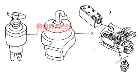
(12) the outline of the battery, loudspeaker and power supply (see as figure 14)
(View)
View full Circuit Diagram | Comments | Reading(362)
CM6800 and CM6801--the single chip power supply control integrated circuit
Published:2011/7/12 22:35:00 Author:Borg | Keyword: single chip, power supply, integrated circuit


CM6800 and CM6801 are the single chip PFC+PWM control integrated circuit produced by CMC Corp., the USA, which is widely used in PC power supply, air-conditioner, large screen color TV, monitor, UPS and AC adapter, etc.1.function featuresCM6800 and CM6801 have functions of over-voltage protection, over-current protection and over-heat protection, the power factor is close to 1. The PWM in them is added with the current limitation function; 23VBi-coms process has the synchronized leading edge PFC and rear edge PWM, which provides with high switch ratio for rising the reaction speed; the fault amplifier works in a low starting circuit and low working current.
(View)
View full Circuit Diagram | Comments | Reading(3578)
brake lamp delay arrester
Published:2011/7/12 22:30:00 Author:chopper | Keyword: brake lamp, delay arrester
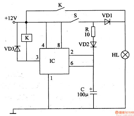
Brake lamp of general motor will light when the brake switch is trampled,and it will extinguish immediately when the brake switch is released.This example describes the brake lamp delay arrester, which can make brake lamp light for some time before it gose out when the brake switch is released,and it can avoidthe vehicle rear-end collision efficiently,and increase traffic safety. The principle of circuitThis brake lamp delay arrester includes time-base integrated circuit IC,relay K,capacitor C and diode VD1-VD3,which is shown as figure 7-34.
(View)
View full Circuit Diagram | Comments | Reading(562)
| Pages:1543/2234 At 2015411542154315441545154615471548154915501551155215531554155515561557155815591560Under 20 |
Circuit Categories
power supply circuit
Amplifier Circuit
Basic Circuit
LED and Light Circuit
Sensor Circuit
Signal Processing
Electrical Equipment Circuit
Control Circuit
Remote Control Circuit
A/D-D/A Converter Circuit
Audio Circuit
Measuring and Test Circuit
Communication Circuit
Computer-Related Circuit
555 Circuit
Automotive Circuit
Repairing Circuit