
Circuit Diagram
Index 1555
Delay lamp circuit using relay (5)
Published:2011/7/6 22:29:00 Author:zj | Keyword: Delay lamp circuit, using relay

As shown in the figure, K adopts JRX-13F, DC12V. (View)
View full Circuit Diagram | Comments | Reading(713)
electronic compass FNN-3300
Published:2011/6/18 9:55:00 Author:Nancy | Keyword: electronic compass

Product features:1.compass measures the plane geomagnetic field and dual axle angle compensation by the three axis magnetic resistance sensor.2.high speed and high accuracy A/D conversion and magnetic field measurement accuracy 100μGuass.3.compass is built in temperature compensation and reduces the temperature drift of the angle of inclination and direction in the maximum limit.4.compass is built in microprocessor sensor and magnetic north angle and outputs RS232 data frame. RS485 and RS422 are available. 5.simple and effective user calibration instruction6.pointing to zero correction function7.containment structure is waterproof and non-magnetic (non-containment structure is available).8.operating temperature range: -40℃ to +85℃; storage temperature range:-55℃ to +100℃.
Product application:Electronic compass FNN-3300 is widely used in airplane and navigation, communication radar, microwave direction,offshore platform control, unmanned machine and robot automatic control and traffic vehicle detection. (View)
View full Circuit Diagram | Comments | Reading(538)
Three terminals capacitor applied circuit diagram
Published:2011/6/14 7:22:00 Author:Sophia | Keyword: Three terminals capacitor, 10DB
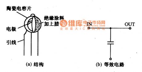
High pass filter of high-frequency circuit usually adopts ceramic capacitor. in the practical designing, the selection of capacitance is very important, the function is different according to the different frequency. so the high pass filter should be designed according to eleminating high freguency noise and reduceing the unneccesary radiation quantity. The high pass filter can get excellent performance by using the Three terminals capacitor .
The structure and equivalent circuit of Three terminals capacitors is showed as the below chart. The electrode of the capacitor connects the U lead, and the anode of the capacitor is the input and output end. When working, the U lead connects the mainsside and the terminals for power supplies of the opposite lead near the electronic device connects human. If the connection is good, the attenuation performance can improve to 10dB.
(View)
View full Circuit Diagram | Comments | Reading(605)
Switching power supply thick film integrated circuit diagram
Published:2011/6/14 7:23:00 Author:Sophia | Keyword: Switching power supply, thick film integrated circuit
STR一D6601 produced by Sanken company is Switching power supply thick film integrated circuit. The improved products of STR一D6601 is widely used in Hitach and Furistock 64cm color TV and VCD, DVD player.
1. The function and characteristics of STR一D6601STR一D6601 integrated circuit contains distributary, driving circuit and high-power switching tube. The peak power output reaches 120w.
2. The function and data of the pin
STR一D6601 integrated circuit adopts single-row pin capsulation, the function and data of its integrated circuit is shown by the chart 1.
note: the output power of STR-D6601 is larger than that of FbSTR-6601, so FbSTR-6601 can replace STR-6601,never the other way around
(View)
View full Circuit Diagram | Comments | Reading(767)
STR D5095A Switching power supply thick film integrated circuit diagram
Published:2011/6/14 7:23:00 Author:Sophia | Keyword: STR D5095A Switching power supply, thick film integrated circuit

STR一D5095A produced by Sanken company is low power consumption and high-power Switching power supply thick film integrated circuit and is widely used in Hitach sz large screen movement of color TV.
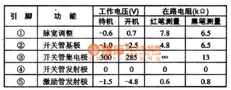
1. The function and characteristicsSTR一D5095A integrated circuit contains sampling, erro amplification, driving circuit, high-power switchiing tube and some other miscellaneous function.
2. The function and data of the pinthe function and data of its integrated circuit is shown by the chart 1. the resistance of the circuit:red pen measurement means that the black probe connects 1 pin. the red probe connect the value of the measured pin;black probe mesurement means that red probe connects 1 pin. Black probe connects the resistance value of the measured pin. (View)
View full Circuit Diagram | Comments | Reading(3421)
Voltage follower cosisted of operational amplifier circuit diagram
Published:2011/6/16 23:17:00 Author:Sophia | Keyword: Voltage follower, Operational amplifier

Voltage follower consisting of operational amplifier circuit is very simple. The circuit doesn't need external components, but can generate oscillation easily. The diagrm is a Voltage follower consisting of smoothly JFET based operational amplifier NJM2082D. If the input and output terminals of the Voltage follower respectively connect 100pF capacitor namely distributed capacitance of imitated wiring. But the circuit still can generate oscillation.
(View)
View full Circuit Diagram | Comments | Reading(761)
Power supply, starting, igniting, instrumentation, signal basic circuit diagram of Beijing
Published:2011/7/7 4:30:00 Author:Sophia | Keyword: Power supply, starting, igniting, instrumentation, signal basic circuit, Beijing
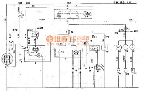
1. Ignition switch
Ignition switch 7 is JR424-type. It is used to connect or disconnect the starter, ignition and electrical lines, and it has four locations: 0 position (off position): The key can only be inserted into or set aside in this position. I position (power position): After starting the engine, It connects the ignition circuit to maintain the normal operation position. Ⅱ position (starting position): This position is to start the engine, when hands is loosened. The key will be automatically returned to power position I. Ⅲ position (attachment position): the engine is not running, the cassette players and other appliances need to be used. The ignition switch will be transfered to this position.
2. Distributor
Distributor9 is FDl3 type, direction of rotation is counter-clockwise direction. firing interval is 90 ° -1 °, the adjustment angle of octane number is 12 °, the contact clearance is 0.35 -0 · 5mm. breaker arm spring pressure is 4.9-6 · 86N; the maximum speed of continuous firing (in the distributor shaft calculated) is 2300r/min, the maximum centrifugal advance angle is 10 ° -13 °, the engine ignition sequence is 1-2-4-3, capacitors is DR203A-type, 12V, 0.20 -0 · 25μF.
3 ignition coil Ignition coil 8 is DQO7A type or DQ148 type. Primary voltage is l2V, secondary voltage is 150OOV more.When wind motoris running, warm air flows from defrost mouth.
(View)
View full Circuit Diagram | Comments | Reading(536)
FET bandwidth amplifier circuit
Published:2011/7/10 2:27:00 Author:leo | Keyword: FET, Bandwidth, Amplifier circuit

Picture 1 shows a FET bandwidth amplifier circuit. In this circuit, VT1 and VT2 are bumpers. VT1 is used as source follower, while VT3 and VT4 are used to amplifying voltage and VT5 and VT6 have the function of power amplifying. A1 is DC feedback circuit which is used to stabilize the circuit. And A1 compares the output signals and input signals and amplifies the difference of them. The amplified signals offer differential to VT2, as a result, VT1 channel current is permitted to form a circle. And this demands that the UGS of VT1 should be matched with input and output voltage of the circuit. (View)
View full Circuit Diagram | Comments | Reading(985)
The low humidity detecting circuit adoptted humicap CGS-H
Published:2011/7/10 2:28:00 Author:leo | Keyword: Low humidity, Detecting circuit

Picture 1 shows a circuit that uses the feature of low humidity of CGSH humicap to test other circuit. This circuit can even test other circuits with high accuracy under the atmosphere with less than 10% humidity. Operation amplifier A1, A2 and A3 are front amplifying circuit and difference amplifying circuit. The output signals of A1 pass through analog switch B1 and be alternately sent to A2 and A3 in order to eliminate the influence of change of temperature and the frequency noise and test steadily the output signals of sensor. A4,A5 and A6 are linear regulating circuit of sensor CGS-H and compensate the temperature by using the thermistor RL. (View)
View full Circuit Diagram | Comments | Reading(650)
LM2468TA-The video final stage integrated circuit
Published:2011/7/10 2:30:00 Author:leo | Keyword: Video, Final stage, Integrated circuit

LM2468TA is a kind of video final stage integrated circuit made by America national semiconductor company. It is widely used in color screen of computer.
Inner circuit diagram. The integrated circuit LM2468TA has three fundamental color signal amplifier circuit and video intensifier stage power supplier circuit and so on. The inner circuit diagram of this integrated circuit is shown in the picture.
Pin function and dataThe integrated circuit LM2468TA uses 9 pin single-line package. The pin function and related data of integrated circuit are shown in the picture. (View)
View full Circuit Diagram | Comments | Reading(697)
LA4520-Single chip stereo player integrated circuit diagram
Published:2011/7/10 22:59:00 Author:leo | Keyword: Single chip, stereo player


LA4520-Single chip stereo player integrated circuit diagram LA4520 is a single chip player integrated circuit. It is widely used in all kinds of players. LA4520 inner circuit diagram and pin functions:LA4520 inner circuit contains two similar playing fronted amplifier circuits, power amplifier circuits and so on. As picture 1 shows, this IC uses 20 pin dual line package and related information are shown in the picture. LA4520 classic applying circuit: the picture 2 shows its classic applying circuits.
(View)
View full Circuit Diagram | Comments | Reading(1630)
The FET chopping amplifier circuit
Published:2011/7/10 2:20:00 Author:leo | Keyword: The FET chopping amplifier circuit, AC amplifier

Picture 1 shows a FET chopping amplifier circuit. Chopping amplifier is made up of chopping part, AC amplifier, and modulator and so on. In this circuit, 3SK38A(VT1 and VT2) is specially developed for FET with grid-source light current and small capability . It is enhancement mode component with the maximum voltage value of 3V. The multivibrator made up of VT5 and VT6 generates square-wave signals which pass through the trigger formed by VT5 and VT6 to be reshaped. After reshaped, the signals are added to the grid of VT1 to be modulated and the modulating frequency is 185Hz. (View)
View full Circuit Diagram | Comments | Reading(951)
Changing Rate Control Circuit of Variable Converting Speed
Published:2011/6/14 13:00:00 Author:Michel | Keyword: Variable Converting Speed, Changing Rate Control
Circuit's FunctionsThis type of circuit uses a certain rate to limit rapid changing signal which can change electrical signals into part of mechanical signal output circuit.Converting speed depends on integral constants and if conversion speed is required to be variableand it usually comes out by changing integrating resistor.This circuit parts the integral input voltgae to alter time constants.
Circuit's Work PrincipleOP amplifier A1 is voltage comparator,A1 is saturated around +VO when the positive potential is input because reverse phase input grounds. (View)
View full Circuit Diagram | Comments | Reading(483)
Double Op-amp Producing Audio Signal Generator Circuit
Published:2011/6/14 13:02:00 Author:Michel | Keyword: Double Op-amp, Producing Audio, Signal Generator Circuit

The sine wave signal generator is often used in test for audio equipment.Hereby,the sine wave signal generator composed of a double op-amp integrated circuit is introduced.This generator has simple circuit,small total harmonic distortion ,supply and the frequency coverage is 76Hz~16kHz.And it uses uses single power supply.
The picture 1 is sine wave signal generator circuit.This circuit is composed of bridge T oscillating circuit,buffer amplifier, neutral voltage generator circuit.The picture's left is oscillating circuit.There is a bridge T circuit between the integrated amp's ① pin and② pin(reversed-phase input terminal) and oscillation frequency is altered via altering bridge T circuit's reference. (View)
View full Circuit Diagram | Comments | Reading(543)
A window comparator circuit made by LTCl042
Published:2011/7/10 2:12:00 Author:leo | Keyword: A window comparator circuit, integrated capacitor

The picture shows a window comparator circuit made by LTCl042. In this circuit, LTC1042 is the window comparator which is used to test integrator and carry out the original reset of it according to the different needs. The first condition of integrator is to select the accuracy of the time periods it needs. After this, the second step is to select the components that can meet the needs of the accuracy, especially the operation amplifier and integrated capacitor. For example, to the operation amplifierμA741 with input differential current of 80 nA, its inaccuracy is 1% when the time period is 0.25 s, however, to LTC1152 with input differential current of 100 pA, its inaccuracy is 1% when the integrated time period is 200 s. In order to improve the accuracy, integrated capacitor uses polystyrene, polytetrafluoroethylene(PTFE) and so on. (View)
View full Circuit Diagram | Comments | Reading(983)
Automatic Transmission Circuit One of Soueast Lioncel
Published:2011/7/8 21:39:00 Author:Michel | Keyword: Soueast Lioncel, Automatic Transmission, Circuit One

Automatic Transmission Circuit of Soueast Lioncel (View)
View full Circuit Diagram | Comments | Reading(654)
Automatic Transmission Circuit Two of Soueast Lioncel
Published:2011/7/8 21:40:00 Author:Michel | Keyword: Lingshuai Cars, Automatic Transmission, Circuit Three

Automatic Transmission Circuit of Soueast Lioncel (View)
View full Circuit Diagram | Comments | Reading(621)
Multichannel Sampling Circuit
Published:2011/6/15 8:46:00 Author:Michel | Keyword: Multichannel, Sampling Circuit

Multichannel Sampling Circuit
The picture is a practical example of multichannel sampling circuit.It consists of 16 channel analog switch, AD7506 type chip, sampling keeping circuit LF398 and AD converter, ADC-0808 and it connects with 1 / O interface chip INTEL8255 parallel port.PA0 ~ PA7 and ADC0808 data is linked together, which is used for data input.PB0 ~ PB4 is channel selection signal which controls the input channel choice.PB5 is the keeping signal, PB6 sampling is the starting signal of A/D converter conversion.PC0 is the end signal input port of A/D converter which is judged by CPU read.Multichannel sampling circuit's work is controlled by corresponding program completely.This circuit has the following kinds of work entirely controlled by the corresponding programs and it has following work ways.
First,sampling in order.It scans sampling aacording to channel sequence.Second,fixed-point sampling.It samples to one fixed channel.Third,setting sampling interval.If the actual measured input signal is less than channel numbers of sampling system , the sampling interval can be narrowed. (View)
View full Circuit Diagram | Comments | Reading(1019)
Cadmium Nickel Battery Charging Circuit of Automatic Control and Constant Current Charging
Published:2011/6/15 9:08:00 Author:Michel | Keyword: Automatic Control, Constant CurrentCharging, Cadmium Nickel, Battery Charging Circuit

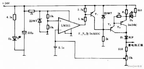
This circuit adopts automatic control,and constant current charging method.The nominal voltage of charged battery is 10V and its end-of-charge voltage is 12V.T2, T3, and related components consistitutes constant current source and the current value is approximate 4.8 V/R1.Diode D1 is set to prevent the battery discharges when AC power goes off or rectifier circuit breaks down.LM311 is comparator outputs low PWL when it reaches setting value fter being charged and T1 saturates and conducts,T2 stops,constant current sources stops working and the charging stops.
LED,D2 brights,D3 is used as source indication when it is charging. (View)
View full Circuit Diagram | Comments | Reading(2052)
Switch Power Supply Circuit of Operational Amplifier A741
Published:2011/6/15 10:40:00 Author:Michel | Keyword: Operational Amplifier, Switch Power Supply, Circuit

The picture shows a novel design of switch power.The power adopts operational amplifier A741 as comparing control elements, two transistor as adjustable components and the circuit work in switch state.When the output voltage is 2mV lower than benchmark low voltage,in other words,μA741 ② feet is 2mV lower than ③ feet(Because μA741 response sensitivity is 2mV),μAT41 ⑥ feet outputs high PWL,control VT1 and VT2 conduct and load with large current and relevant filter capacitors,C2 and C3 supply power which makes output voltage increases to 12V,that's to say,both μA741 ② and ③ feets' potential are equal.The⑥ feet outputs low voltage (2 V), VT1, VT2 close and it suspends supply electric power.As the time goes by, the output voltage drops grdually and repeats the aboved process,the power keeps in swtich state and the output voltage is 12V all the time. (View)
View full Circuit Diagram | Comments | Reading(1287)
| Pages:1555/2234 At 2015411542154315441545154615471548154915501551155215531554155515561557155815591560Under 20 |
Circuit Categories
power supply circuit
Amplifier Circuit
Basic Circuit
LED and Light Circuit
Sensor Circuit
Signal Processing
Electrical Equipment Circuit
Control Circuit
Remote Control Circuit
A/D-D/A Converter Circuit
Audio Circuit
Measuring and Test Circuit
Communication Circuit
Computer-Related Circuit
555 Circuit
Automotive Circuit
Repairing Circuit