
Circuit Diagram
Index 1547
TEANA A33-EL Taillight Circuit Two
Published:2011/7/14 8:49:00 Author:Joyce | Keyword: TEANA , Taillight

TEANA A33-EL Taillight Circuit (View)
View full Circuit Diagram | Comments | Reading(551)
TEANA A33-EL Headlamp Light Control Circuit One
Published:2011/7/14 8:52:00 Author:Joyce | Keyword: TEANA , Headlamp , Light Control

TEANA A33-EL Headlamp Light Control Circuit (View)
View full Circuit Diagram | Comments | Reading(568)
TEANA A33-EL Headlamp Light Control Circuit Two
Published:2011/7/14 8:53:00 Author:Joyce | Keyword: TEANA, Headlamp , Light Control

TEANA A33-EL Headlamp Light Control Circuit (View)
View full Circuit Diagram | Comments | Reading(609)
TEANA A33-EL Headlamp Light Control Circuit Three
Published:2011/7/14 8:55:00 Author:Joyce | Keyword: TEANA, Headlamp , Light Control

TEANA A33-EL Headlamp Light Control Circuit (View)
View full Circuit Diagram | Comments | Reading(616)
TEANA A33-EL Charging System Circuit
Published:2011/7/14 8:59:00 Author:Joyce | Keyword: TEANA , Charging System

TEANA A33-EL Charging System Circuit (View)
View full Circuit Diagram | Comments | Reading(666)
TEANA A33-EL Starting System Circuit
Published:2011/7/14 9:00:00 Author:Joyce | Keyword: TEANA , Starting System

TEANA A33-EL Starting System Circuit (View)
View full Circuit Diagram | Comments | Reading(595)
TEANA A33-EL Loudspeaker Circuit
Published:2011/7/14 9:01:00 Author:Joyce | Keyword: TEANA , Loudspeaker

TEANA A33-EL Loudspeaker Circuit (View)
View full Circuit Diagram | Comments | Reading(634)
The turning and danger signal connection circuit of Santana 2000 (gasoline injection engine)
Published:2011/7/12 20:35:00 Author:Borg | Keyword: danger signal, Santana 2000
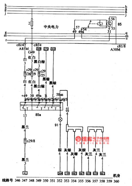
Figure: The turning and danger signal connection circuit of Santana 2000(gasoline injection engine)85-turning and danger signal flash relay; 85a-warning signal lamp switch; 91-the internal lighting lamp of warning lamp switch (View)
View full Circuit Diagram | Comments | Reading(418)
CX2O106A--the infrared tracking and control reception integrated circuit
Published:2011/7/12 3:14:00 Author:Borg | Keyword: infrared, integrated circuit
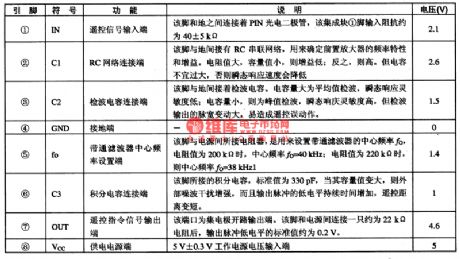
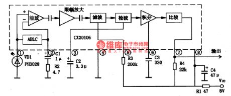
CX2O106A is an infrared tracking and control reception integrated circuit produced by Sony, Japan, which is widely used in the video, audio, air-conditioning, fan and so on as the remote signal reception circuit.1.pin functions and dataCX2O106A contains the remote signal reception, bandpass filtering, aftermath and other circuits. This IC is in 8-pin package, whose pin functions and data are listed in table 1.
Table 1.pin functions and data of CX20106A2.the internal circuit and typical application circuit
(View)
View full Circuit Diagram | Comments | Reading(690)
The turning indicator connection circuit of Santana 2000(gasoline injection engine)
Published:2011/7/12 20:31:00 Author:Borg | Keyword: turning indicator, Santana 2000
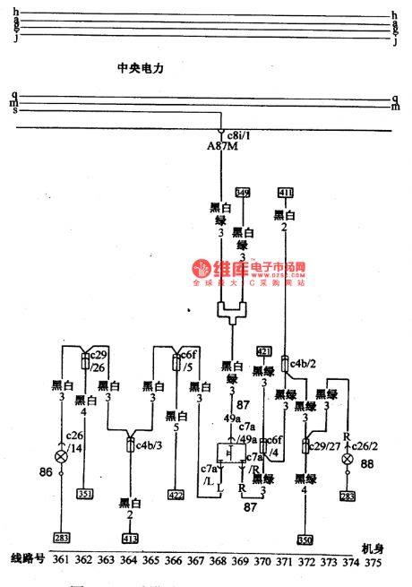
Figure: The turning indicator connection circuit of Santana 2000(gasoline injection engine)86-left turning indicator; 87-turning lamp switch; 88-right turning indicator (View)
View full Circuit Diagram | Comments | Reading(419)
KA9270--the dual channel audio filter integrated circuit
Published:2011/7/12 2:43:00 Author:Borg | Keyword: dual channel, audio filter, integrated circuit

1. The internal circuit and pin functions of KA9270 KA9270 contains the impedance buffer, low-pass filter, de-weight control motor, basic pole voltage circuit, whose internal circuit is shown in figure 1-1. The IC is in 20-pin dual line structure, which has two forms marked with suffix letters, the one without suffix is dual in-line package, and the other one with D suffix is flat dual line package, the pin functions of them are the same, see as table 1-1.Figure 1-1 the internal circuit of KA9270/D
(View)
View full Circuit Diagram | Comments | Reading(2205)
The rear combined lamp wiring circuit of Santana 2000(gasoline injection engine)
Published:2011/7/12 20:27:00 Author:Borg | Keyword: rear combined lamp, gasoline injection engine
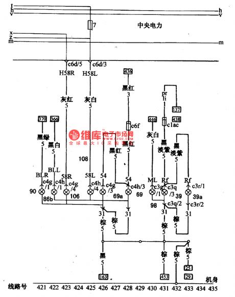
Figure: The rear combined lamp wiring circuit of Santana 2000(gasoline injection engine)39-left backup lamp; 39a-right backup lamp; 69-left brake signal lamp; 69a-right brake signal lamp; 86a-left rear turning signal lamp; 90-right rear turning signal lamp; 106-right tail lamp; 108-left rail lamp; 98-rear fog lamp. (View)
View full Circuit Diagram | Comments | Reading(446)
The fog lamp, back-up lamp and brake lamp switch wiring circuit of Santana 2000(gasoline injection engine)
Published:2011/7/12 20:04:00 Author:Borg | Keyword: fog lamp, back-up lamp, brake lamp switch
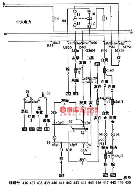
Figure: The fog lamp, back-up lamp and brake lamp switch wiring circuit of Santana 2000(gasoline injection engine)
38-backup lamp switch; 68-brake linked switch; 94-fog lamp relay; 95-left fog lamp; 96-right fog lamp; 97-fog lamp switch; 99-the lighting lamp of fog lamp switch (View)
View full Circuit Diagram | Comments | Reading(661)
The license lamp and instrument lamp wiring circuit of Santana 2000(gasoline injection engine)
Published:2011/7/12 20:27:00 Author:Borg | Keyword: license lamp, instrument lamp
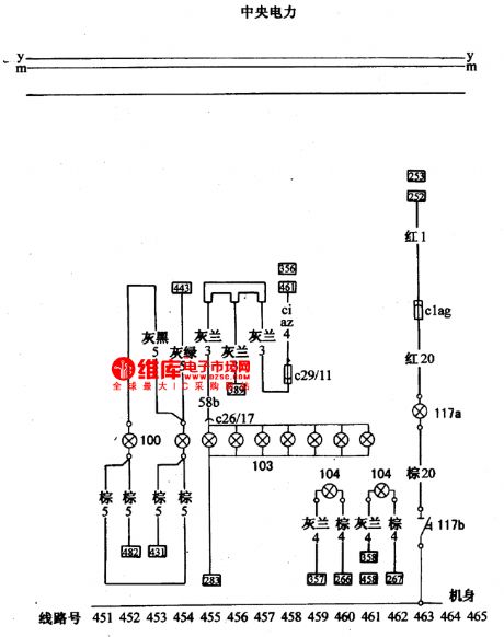
Figure: The license lamp and instrument lamp wiring circuit of Santana 2000(gasoline injection engine)100-license lamp; 103-instrument lighting lamp; 104-ventilation system lighting lamp; 117a-engine under shell lamp; 117a-engine under shell lamp switch. (View)
View full Circuit Diagram | Comments | Reading(437)
L4962A--the efficient DC-DC converting integrated circuit of single chip
Published:2011/7/12 2:10:00 Author:Borg | Keyword: single chip, integrated circuit
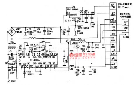

1.function featuresThe switching efficiency of L4962A is about 80%, the working frequency is over 100MHZ, it has very few external elements, and its output current can be 1.5V, the output voltage can also be regulated in the range of 5-OV. It contains the precise voltage basic pole, fault amplifier, comparator and power switch, and it also includes the slow starting, max current limit and over heat protection circuit, etc. The typical application circuit of it is shown in figure 1-1.
2.pin function and dataL4962A is in the 16-pin dual in-line package.
(View)
View full Circuit Diagram | Comments | Reading(1482)
The reading lamp and internal lamp wiring circuit of Santana 2000(gasoline injection engine)
Published:2011/7/12 20:28:00 Author:Borg | Keyword: reading lamp, internal lamp, gasoline injection engine
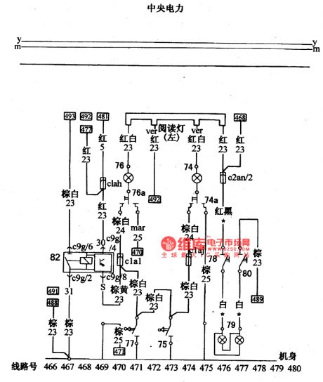
Figure: The reading lamp and internal lamp wiring circuit of Santana 2000(gasoline injection engine)74-reading lamp; 74a-reading lamp switch(right); 75-right door control switch; 76-reading lamp; 76-reading lamp switch (left); 77-left door control switch; 78-sun glasses veil lighting lamp switch (Ⅰ); 78-sun glasses veil lighting lamp; 80-sun glasses veil lighting lamp switch (Ⅱ); 82-internal lamp time relay. (View)
View full Circuit Diagram | Comments | Reading(444)
The trunk lamp and tool case wiring circuit of Santana 2000(gasoline injection engine)
Published:2011/7/12 20:28:00 Author:Borg | Keyword: trunk lamp, wiring circuit
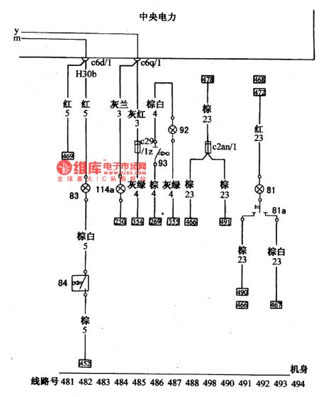
Figure:The trunk lamp and tool case wiring circuit of Santana 2000(gasoline injection engine)81-driving cab lamp; 81a-room lamp switch; 93-trunk lamp; 84-trunk lamp contactor switch; 92-tool chamber lamp; 93-tool chamber lamp switch; 114a-cigarette lighter lamp. (View)
View full Circuit Diagram | Comments | Reading(404)
instrument-panel lamp dimmer
Published:2011/7/12 22:29:00 Author:chopper | Keyword: instrument-panel lamp, dimmer
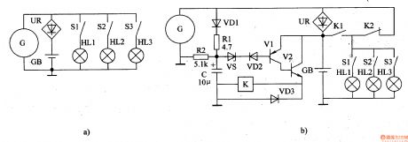
Drivers may feel very harsh at the moment the instrument-panel lamp is open at night.This example describes the instrument-panel lamp dimmer,which can reduce the visual impact of the drives,thereby it can enhance the safety of night driving. The principle of circuitThe instrument-panel lamp dimmer circuit is formed by the voltage regulator circuit,reset circuit,square-wave oscillator,protection circuit and electronic switching circuit,which is shown in figure 7-35. Regulator circuit consists of resistorsR1 and the voltage regulator diode VS. Reset circuit consists of capacitor C1, resistors R3, R4.
(View)
View full Circuit Diagram | Comments | Reading(629)
bean sprout automatic watering thermostat
Published:2011/7/13 22:13:00 Author:chopper | Keyword: bean sprout, automatic watering, thermostat
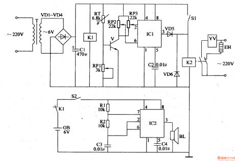
It should control the growth temperature and water at regular time when we produce bean sprout,and the manual operation is relative complicated. This example describes the bean sprouts automatic watering thermostat, with outage alarm function.It can automatically control the growth temperature of bean sprouts, and can water bean sprout by the temperature automatically,thus the bean sprouts can grow in an optimal growth temperature range. The principle of circuitThis bean sprout automatic watering thermostat is formed by the power supply circuit,the temperature detection control circuit and outage alarm circuit, which is shown in figure 4-207.
(View)
View full Circuit Diagram | Comments | Reading(1461)
timing controller(2)
Published:2011/7/13 22:02:00 Author:chopper | Keyword: timing controller
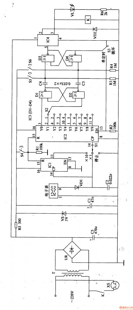
The timing controller described in this example is of functions like time display,cycle timing, single timing,and manual function,and the regular timing time is 1-90min.It can be used to control a variety of electrical equipments which should work at regular time or work intermittently. The principle of circuit The timing controller circuit is formed by the power supply circuit, the clock signal generator,counting distributor,RS trigger and the switch output circuit, which is shown in figure 4-165.
(View)
View full Circuit Diagram | Comments | Reading(572)
| Pages:1547/2234 At 2015411542154315441545154615471548154915501551155215531554155515561557155815591560Under 20 |
Circuit Categories
power supply circuit
Amplifier Circuit
Basic Circuit
LED and Light Circuit
Sensor Circuit
Signal Processing
Electrical Equipment Circuit
Control Circuit
Remote Control Circuit
A/D-D/A Converter Circuit
Audio Circuit
Measuring and Test Circuit
Communication Circuit
Computer-Related Circuit
555 Circuit
Automotive Circuit
Repairing Circuit