
Circuit Diagram
Index 1549
wireless remote control switch circuit(six)
Published:2011/7/12 7:12:00 Author:Lena | Keyword: wireless, remote control, switch
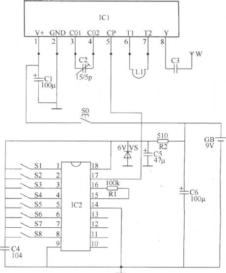
The wireless remote control switch introduced in the text has these features: great emitter power, high sensitivity, low manufacture cost, the max remote control distance can reach 500m. The switch can be used as control switch of lamps and household appliance, and the switch can also be used to control electric toys.
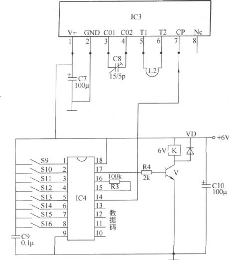
This wireless remote control switch circuit consists of wireless remote control transmitting circuit and wireless remote control receiving circuit two parts.
The wireless remote control transmitting circuit shown in the figure consists of data/encrypted code integrated circuit IC2, wireless remote control transmitting integrated circuit IC1, resistor R1,R2, capacitor C1-C6, steady pressure diode VS, control button S0, coding switch S1-S8, oscillator coil L and antenna W.
(View)
View full Circuit Diagram | Comments | Reading(1430)
remote control tri-proportion controller circuit
Published:2011/7/12 7:37:00 Author:Lena | Keyword: remote control, tri-proportion controller
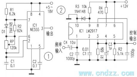
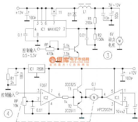
The tri-proportion controller is used to control electromotor rotate speed or oil plants engine accelerograph bulk etc in various power remote control models. Here introduces code/encode and control circuit which can realize above functions.This device realizes the remote tri-proportion control by altering transmitter modulation frequency. Figure 1 is the transmitter frequency regulation circuit, altering the bulk of potentiometer RP can make oscillator frequency change between 100Hz and 1 kHz, the output end of this circuit connects modulation input of high frequency transmitter.
(View)
View full Circuit Diagram | Comments | Reading(680)
radio frequency chip RF401 and constituted high credibility remote control circuit
Published:2011/7/12 3:40:00 Author:Lena | Keyword: radio frequency chip, high credibility, remote control
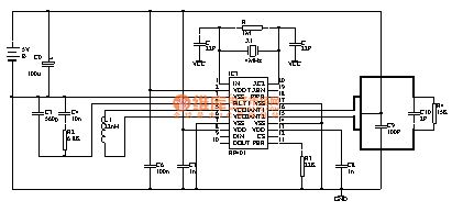
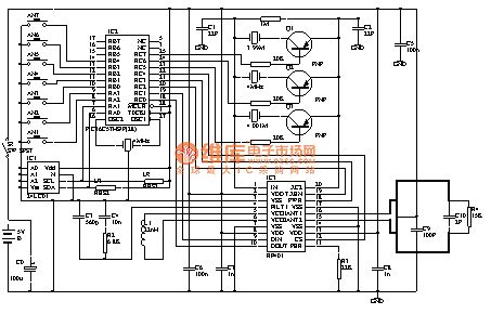

RF401 is Norway Nordic company newly protrusive data transmission band 433MHZ single piece wireless transceiver chip, this chip integrates high frequency transmitting, high frequency receiving, PLL synthesization, FSK modulation, FSK demodulation, multi-channel switch etc function, and has excellent performance, low power loss, easy usage etc features. Periphery components of nRF401 are very few, only involve one criterion crystal oscillator and few passive devices without debugging parts, this brings huge convenience for development and manufacture.Table 1 is NRF401 electric performance parameters.Table 2 is NRF401 pin function diagram.
Paremeters
Value
Unit
工作频道
433.92/434.33
MHz
调制方式
FSK
频偏
15
KHz
谢频输出功率 0.4k,3v
10
dBm
接收灵敏度 0.4k,BR=20 kbit/s BER<10
-105
dBm
最大传送数码率
20
K bit/s
适用电压范围
2.7~5.25
V
接收状态功耗
250
uA
发射状态功耗 -10 dBM
8
mA
等待状态功耗
8
8uA