
Circuit Diagram
Index 1546
TEANA A33-EL Meter Circuit
Published:2011/7/14 9:06:00 Author:Joyce | Keyword: TEANA , Meter

TEANA A33-EL Meter Circuit (View)
View full Circuit Diagram | Comments | Reading(637)
TEANA A33-EL Lighting Circuit One
Published:2011/7/14 9:07:00 Author:Joyce | Keyword: TEANA , Lighting

TEANA A33-EL Lighting Circuit (View)
View full Circuit Diagram | Comments | Reading(582)
TEANA A33-EL Lighting Circuit Two
Published:2011/7/14 9:09:00 Author:Joyce | Keyword: TEANA , Lighting

TEANA A33-EL Lighting Circuit Two (View)
View full Circuit Diagram | Comments | Reading(580)
TEANA A33-EL Turn Light Circuit One
Published:2011/7/14 9:10:00 Author:Joyce | Keyword: TEANA , Turn Light

TEANA A33-EL Turn Light Circuit (View)
View full Circuit Diagram | Comments | Reading(576)
TEANA A33-EL Turn Light Circuit Two
Published:2011/7/14 9:11:00 Author:Joyce | Keyword: TEANA , Turn Light

TEANA A33-EL Turn Light Circuit (View)
View full Circuit Diagram | Comments | Reading(570)
TEANA A33-EL Turn Light Circuit Three
Published:2011/7/14 9:13:00 Author:Joyce | Keyword: TEANA , Turn Light

TEANA A33-EL Turn Light Circuit (View)
View full Circuit Diagram | Comments | Reading(647)
TEANA A33-EL Turn Light Circuit Four
Published:2011/7/14 9:14:00 Author:Joyce | Keyword: TEANA , Turn Light

TEANA A33-EL Turn Light Circuit (View)
View full Circuit Diagram | Comments | Reading(569)
The capacitance test circuit composed of LM741
Published:2011/7/14 4:57:00 Author:Borg | Keyword: capacitance, test circuit
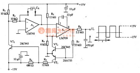
In figure 8-3 is the capacitance test circuit composed of LM741. The test principle of the circuit that the capacitor Cx under test is charging/discharging to generate a triangular wave, if the period of the wave is tested, the volume of the capacitor is known. The Miller integrating circuit can be composed of A1, and the Miller circuit composed of A2 is forming forward and backward feedbacks so the oscillation is generated, whose amplitude is decided by R4 and R3, equal to 1/3 of the power supply voltage. The charge current of Cx is decided by power supply circuit and R2, the discharging current is decided by the power supply voltage and (R1+R2). In principle, oscillating is not affected by the power supply voltage.
(View)
View full Circuit Diagram | Comments | Reading(1764)
TEANA A33-EL Lighting Circuit Three
Published:2011/7/14 9:15:00 Author:Joyce | Keyword: TEANA , Lighting

TEANA A33-EL Lighting Circuit (View)
View full Circuit Diagram | Comments | Reading(566)
TEANA A33-EL Lighting Circuit Four
Published:2011/7/14 9:16:00 Author:Joyce | Keyword: TEANA , Lighting

TEANA A33-EL Lighting Circuit (View)
View full Circuit Diagram | Comments | Reading(540)
Subtraction Circuit of Two Operational Amplifiers Input from Inphase End
Published:2011/7/11 2:18:00 Author:Joyce | Keyword: Subtraction, Operational Amplifiers, Inphase End
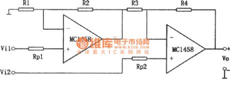
As shown in the figure is a subtraction circuit of two operational amplifiers input from inphase end. According to the circuit analysis, the relationship between input and output is as follows:
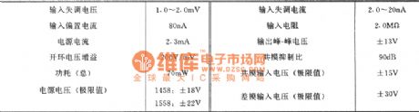
The typical values of main parameters of series 1458/1558: (View)
View full Circuit Diagram | Comments | Reading(551)
The peak value detection circuit composed of FET
Published:2011/7/14 1:09:00 Author:Borg | Keyword: peak value, FET

The circuit consists of the forward/negative peak value circuit and difference amplifier. A1 keeps the forward voltage at the max value, the voltage is represented at point a. A2 keeps the backward voltage at the max value, the voltage is represented at point b. A3 is the difference amplifier whose gain is 1, it can amplifier the voltage Ua at point a and Ub at spot b, by which the forward/backward peak value of the input voltage Ui can be got. The maintenance time of the circuit is decided by the grid current leakage of C1 or C2, VD1 or VD2, VT1 or VT2.
(View)
View full Circuit Diagram | Comments | Reading(692)
The temperature connector circuit of LX5600
Published:2011/7/14 6:19:00 Author:Borg | Keyword: temperature connector
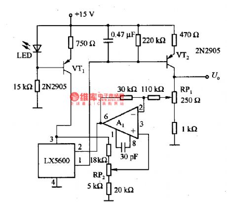
This is the temperature connector circuit of LX5600. In the circuit, LED and VT1 compose the constant current circuit, which provides with working current of LX5600. VT2 is the low output impedance amplifier, which magnifies the output signal of LX5600; A1 is the phase reverser, which completes the backward feedback; RP1 is used to regulate the converting sensibility; RP2 is used to zero set. The output voltage is 0-5v, the temperature of 100℃ is corresponding to the voltage of 4V.
(View)
View full Circuit Diagram | Comments | Reading(1021)
The FSK circuit composed of ME564
Published:2011/7/14 5:29:00 Author:Borg | Keyword: FSK circuit
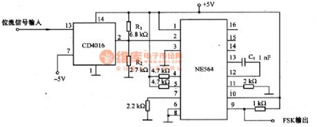
This is the FSK circuit which is composed of ME564. In the circuit, NE564 is a simulating PLL integrated circuit, the FSK modulation is done by CD4016 analog switch which is controlled by dual-state signals. CD4016 makes the 2-pin of NE564 in the voltage of 5V and 1.42V, i.e 5Vx[R2/(R1十R2)]=1.42V. The bias current of the power supply phase detector is controlled by the voltage on 2-pin. Therefore, when the phase is continuous, the output of the VCO can be changed. The capacitor C0 which determines the central frequency of VCO does not change, the drift between FSK frequencies can be adjusted by R1 and R2.
(View)
View full Circuit Diagram | Comments | Reading(2206)
The FSK modulation circuit composed of 74LS74
Published:2011/7/14 5:57:00 Author:Borg | Keyword: FSK modulation
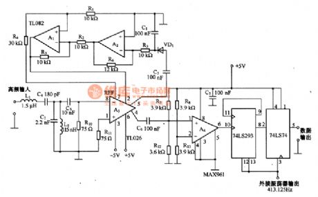
This is the FSK modulation circuit composed of 74LS74. The FSK modulation circuit has neither PLL nor bandpass filter with high Q value, so there is no need of any tune adjustment in the high-frequency modulation circuit. The 2 tune circuits composed of L1, L2, C4 and C7 is working as the input filter, which only allows the frequency band with central frequency of 10MHZ to pass, and the high frequency difference amplifier A3 can amplify the 10MHZ signal. The auto gain control (AGC) circuit is composed of A1 and A2. The HF signal, which is magnified by A3, can be switched into digital signal by comparator A4.
(View)
View full Circuit Diagram | Comments | Reading(3219)
The thermometer circuit composed of LX5600
Published:2011/7/14 6:09:00 Author:Borg | Keyword: thermometer circuit

When this thermometer is used in the room, it can work in the intermittent way, and this working state can be kept in the temperature test circuit, because internal temperature doesn't change sharply. The astable multi-resonance oscillator consists of VT1 and VT2, i.e the interval oscillator circuit, which samples per 1s, and the interval time ratio is 0.2%, the power supply is 8-12V. C1 and R3 decide the block time of the oscillating circuit, C1, R1, R4 and R7 decide the conducting time of the interval oscillating time. (View)
View full Circuit Diagram | Comments | Reading(1581)
The simple fan fault detection circuit
Published:2011/7/14 6:43:00 Author:Borg | Keyword: fan fault, detection circuit
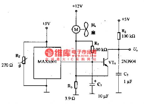
After the circuit is added with a thermistor switch MAX6501, if the system temperature is higher than the regulated value, then it will warn to replace the fan fault detector. RT thermistor should be close to MAX6501 when it is connected in, and it is located in the fan wind, so the fault of stopping running can be detected quickly, the reason is that when the fan is not running, there won't be air to pass RT and MAX6501. The circuit is not fitted in the fan with the closed lock rotator detector. If a fan is fixed with a rotator, the fan will restart in 0.5-1S after it stops. (View)
View full Circuit Diagram | Comments | Reading(1301)
TEANA A33-EL Fault Indicating Lamp and Data Interface Circuit
Published:2011/7/14 8:57:00 Author:Joyce | Keyword: TEANA , Fault Indicating Lamp , Data Interface

TEANA A33-EL Fault Indicating Lamp and Data Interface Circuit (View)
View full Circuit Diagram | Comments | Reading(591)
TEANA A33-EL Stoplight Circuit Two
Published:2011/7/14 8:46:00 Author:Joyce | Keyword: TEANA , Stoplight

TEANA A33-EL Stoplight Circuit (View)
View full Circuit Diagram | Comments | Reading(634)
TEANA A33-EL Taillight Circuit One
Published:2011/7/14 8:47:00 Author:Joyce | Keyword: TEANA , Taillight

TEANA A33-EL Taillight Circuit (View)
View full Circuit Diagram | Comments | Reading(622)
| Pages:1546/2234 At 2015411542154315441545154615471548154915501551155215531554155515561557155815591560Under 20 |
Circuit Categories
power supply circuit
Amplifier Circuit
Basic Circuit
LED and Light Circuit
Sensor Circuit
Signal Processing
Electrical Equipment Circuit
Control Circuit
Remote Control Circuit
A/D-D/A Converter Circuit
Audio Circuit
Measuring and Test Circuit
Communication Circuit
Computer-Related Circuit
555 Circuit
Automotive Circuit
Repairing Circuit