
Circuit Diagram
Index 1551
Practical nickel cadmium battery automatic charger circuit
Published:2011/7/13 22:12:00 Author:TaoXi | Keyword: Practical nickel cadmium battery, automatic charger

The charge which is introduced in this article can supply the stable charging current and it has the timing circuit to control the charging time.
As the figure 4-17 shows, when the press the button SW1, the city electricity is connected, the relay RL1 closes, the red light emitting diode LED2 turns on, this means that the charger has connected with the power. The regulator IC5 supplies the 12V DC voltage to the RL1. The regulator IC2 supplies the +5V voltage to the logic circuit. The constant current source is composed of IC1, it can output the stable charging current. R1 fixes the charging current at 50mA (used to charge the LR06 type storage battery), R6 fixes the charging current at 11mA (used to charge the 9V 6F22 type laminated battery).
(View)
View full Circuit Diagram | Comments | Reading(676)
Practical simple battery automatic charger circuit
Published:2011/7/13 22:37:00 Author:TaoXi | Keyword: Practical, simple, battery, automatic charger

The circuit principle of the charger is as shown in figure 4-18. The 220V AC city electricity is transformed, rectified and filted by this circuit to output the 20V direct current, and this current charges the battery through the three-port voltage stabilizer. The switching circuit TWH8778 can be used to detect the two-end voltage of the battery.
When the charging starts, the voltage of battery is not enough to conduct the TWH8778, the equivalent circuit is as shown in figure 4-19(a). The constant current charges the battery, the constant current value I0=12.5/R, R is one resistance value of the R1-R4. When the battery voltage increases to the set value, the circuit of figure 4-19(b) is automatically converted into the circuit of 4-19(c).
(View)
View full Circuit Diagram | Comments | Reading(683)
Automatic charging, power supply dual-use device circuit
Published:2011/7/13 22:58:00 Author:TaoXi | Keyword: Automatic, charging, power supply, dual-use, device circuit

Operating principle:
The circuit is as shown in figure 4-3, this device uses three pieces of integrated circuits: IC1 is the LM317, the adjustable voltage stabilization power supply is composed of LM317 and other surrounding components, the adjustment range is 1.25V-15V; IC2 is the pulse oscillator which is composed of the time base circuit 555, the duty ratio is 60%; IC3 is the high current and low current charging and discharging conversion control circuit.
After you pressing the button AN, the battery voltage is lower than the gate voltage of D, so D outputs the high level, the transistor V4 conducts, the relay K closes to form the self-protection.
(View)
View full Circuit Diagram | Comments | Reading(611)
SAA3028 infrared remote control code conversion circuit
Published:2011/7/12 7:01:00 Author:Christina | Keyword: infrared, remote control, code, conversion

The SAA3028 is designed as one kind of general infrared remote control code conversion circuit, the main function of it is to change the RC5/RC5 duplex encoded signal into the equivalent binary code.
Features
The power conversion is convenient; Use the power up reset to start it;The data outputs and inputs by the serial transmission mode, the output port is compatible with the I2C bus;It has two data input ports. One of them can only input the RC5 coded signal, another one can only receive the RC5 coded signal or the RC5 number signal;It only receives the signal which meets the RC5/RC5 encoding format;It is in the 16-pin dual-row DIP plastic package.
(View)
View full Circuit Diagram | Comments | Reading(737)
SBXl492-51/52 (TV, video tape recorder, audio equipment, air conditioner and toy) infrared remote control receiving circuit
Published:2011/7/12 7:17:00 Author:Christina | Keyword: TV, video tape recorder, audio equipment, air conditioner, toy, infrared, remote control, receiving circuit
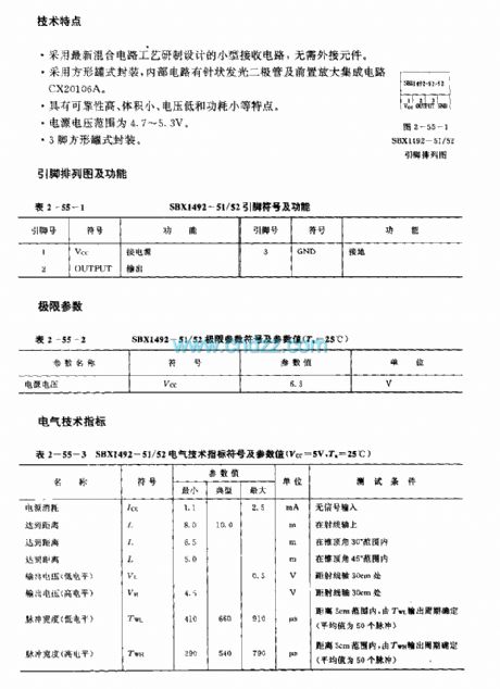
The SBXl492-51/52 is designed as one kind of infrared remote control receiving circuit that can be used in the TV, video tape recorder, audio equipment, air conditioner and toy applications. The carrier frequency of the SBXl492-51 is 40kHz, the carrier frequency of the SBXl492-52 is 38kHz.
Features
It is one kind of small receiving circuit which uses the latest hybrid circuit technology, it does not need the external components;It uses the square tank package, the internal circuit has the needle-like light-emitting diode and the preamplifier IC CX20106A;It has the features of high reliability, small volume and low power consumption;The voltage range of the power is 4.7-5.3V;It is in the 3-pin square tank package.
(View)
View full Circuit Diagram | Comments | Reading(392)
SBX1483—11/12/51/52 (TV, video tape recorder, audio equipment, air conditioner and toy) infrared remote control receiving circuit
Published:2011/7/12 7:24:00 Author:Christina | Keyword: TV, video tape recorder, audio equipment, air conditioner, toy, infrared, remote control, receiving circuit
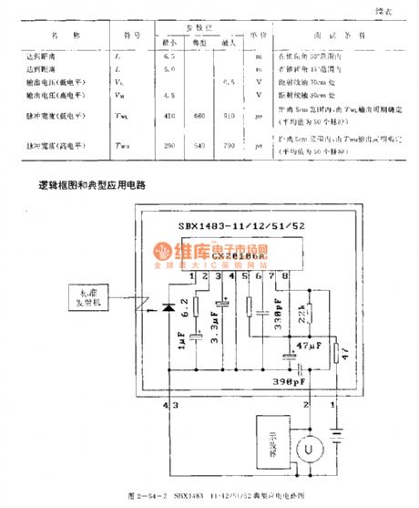
The RX-1387/BX-1407 is designed as one kind of infrared remote control receiving circuit that can be used in the TV, video tape recorder, audio equipment, air conditioner and toy applications. The carrier frequencies of the SBX1483-11 and SBX1483-51 are 40kHz, the carrier frequencies of the SBX1483-12 and SBX1483-52 are 38kHz. The SBX1483-11 and SBX1483-12 use the photoelectric receiving conductive film, and the SBX1483-51 and SBX1483-52 do not use the photoelectric receiving conductive film.
Features:
It is one kind of small receiving circuit which uses the latest hybrid circuit technology, it does not need the external components;It uses the square tank package, the internal circuit has the needle-like light-emitting diode and the preamplifier IC CX20106A;It has the features of high reliability, small volume and low power consumption;The voltage range of the power is 4.7-5.3V;It is in the 4-pin square tank package.
(View)
View full Circuit Diagram | Comments | Reading(1824)
SAFl039P (TV set, audio equipment and industrial control equipment) infrared remote control receiving decoder circuit
Published:2011/7/12 7:36:00 Author:Christina | Keyword: TV set, audio equipment, industrial control equipment, infrared remote control, receiving, decoder
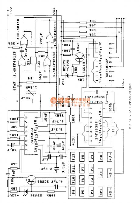
The SAF1032P is designed as one kind of infrared remote control receiving decoder circuit that can be used in the TV set, audio equipment and industrial control equipment applications.
Features
It uses the LOCMOS technology, so the power consumption is small;The static keyboard matrix;32-jump control instruction;It has two kinds of launch modes that can be choosed;The input and output parts can prevent the electrostatic effect in different practical conditions, even so, you need to use it according to the operation rule;It uses the 16-pin dual-row DIP plastic package;The supporting model is SAF1032P.
(View)
View full Circuit Diagram | Comments | Reading(810)
SAFl032F (TV set, audio equipment and industrial control equipment) infrared remote control receiving decoder circuit
Published:2011/7/12 7:58:00 Author:Christina | Keyword: TV set, audio equipment, industrial control equipment, infrared remote control, receiving, decoder
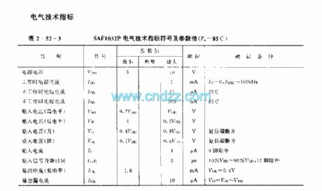
The SAF1032P is designed as one kind of infrared remote control receiving decoder circuit that can be used in the TV set, audio equipment and industrial control equipment applications. The internal circuit is composed of the digital displacement registers (SRDT), the timer counter (CTIM), the comparator, the binary output flag (BWF), the binary selection flag (SELF), the buffer register (BFR), the analog decoder (ANDEC), the linear register (LIN), the comparator counter and the bit counter.
Features
It uses the LOCMOS technology, so the power consumption is small;It uses the single power supply operating mode;It has 16 program selective codes, and it has the anti-error code function;It has the auto-setup function;It has three analog control functions, every control process has 63 steps;The input and output parts can prevent the electrostatic effect in different practical conditions, even so, you need to use it according to the operation rule;It uses the 18-pin dual-row DIP plastic package;The supporting model is SAF1039P.
(View)
View full Circuit Diagram | Comments | Reading(836)
SAAl25l (TV set) infrared remote control receiving amplifier circuit
Published:2011/7/12 8:13:00 Author:Christina | Keyword: TV set, infrared, remote control, receiving amplifier

The SAA1251 is designed as one kind of infrared remote control receiving amplifier P-channel Si integrated circuit, and it can be used in the TV set application. The internal circuit is composed of the oscillator, the clock signal generator, the amplifier, the frequency divider, the direct input circuit, the code converter, the selective decoder, the control device, the D/A converter, the power trigger, the program location memory and the data output register.
(View)
View full Circuit Diagram | Comments | Reading(478)
M58485P (TV and audio equipment) 29 functions infrared remote control receiving circuit
Published:2011/7/12 8:20:00 Author:Christina | Keyword: TV, audio equipment, 29 functions, infrared remote control, receiving circuit
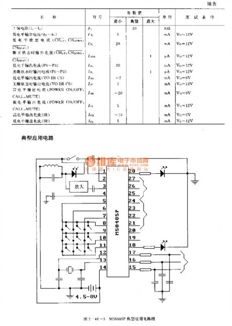
The M58485P is designed as one kind of 29 functions infrared remote control receiving circuit, and it can be used in the TV and audio equipment applications. The internal circuit is composed of the input circuit, the scanner, the modem, the power-on reset circuit, the type encoder, the oscillator, timing signal generator, instruction decoder, channel controller and the D/A converter, and it is in the 28-pin dual-row DIP package.
(View)
View full Circuit Diagram | Comments | Reading(1160)
M58487AP (TV and audio equipment) 24 functions infrared remote control receiving circuit
Published:2011/7/12 8:31:00 Author:Christina | Keyword: TV, audio equipment, 24 functions, infrared remote control, receiving circuit
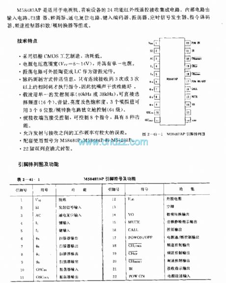

The M58487AP is designed as one kind of 24 functions infrared remote control receiving circuit, and it can be used in the TV and audio equipment applications. The internal circuit is composed of the input circuit, the scanner, the modem, the power-on reset circuit, the type encoder, the oscillator, timing signal generator, instruction decoder, channel controller and the D/A converter.
Features
It uses the aluminum-gate CMOS process, the power consumption is low;The voltage range of the power supply is wide, and it has the single power supply;The oscillation circuit can connect with the ceramic or LC as the resonant component;The good anti-noise performance;The carrier frequency has the single transmitting frequency;The receiving end can control 8 instructions, and it has 8 functions;It allows the operating frequency to have the large error between the transmitter and receiver;It can be used with the M58480P,M58484P and M51231P;It is in the 22-pin dual-row DIP package.
(View)
View full Circuit Diagram | Comments | Reading(879)
M50126P (TV set) infrared remote control receiving circuit
Published:2011/7/12 8:48:00 Author:Christina | Keyword: TV set, infrared remote control, receiving circuit
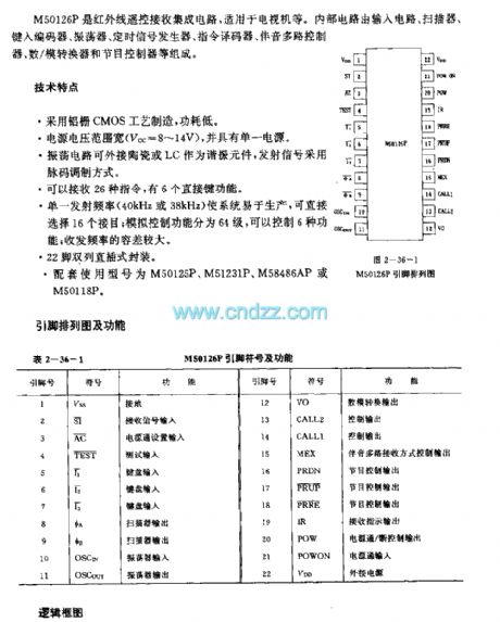
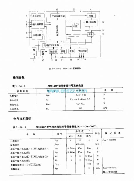
The M50126P is designed as one kind of infrared remote control receiving circuit, and it can be used in the TV set application. The internal circuit is composed of the input circuit, the scanner, the type-in encoder, the oscillator, the timing signal generator, the instruction decoder, the multi-channel audio controller, the D/A converter and the program controller.
Features
It uses the aluminum-gate CMOS process, the power consumption is low;The voltage range of the power supply is wide, and it has the single power supply;The oscillation circuit can connect with the ceramic or LC as the resonant component;The good anti-noise performance;It can receive 26 kinds of instructions, and it has 6 direct button functions;It can be used with the M50125P,M51231P and M58486P, M50118P;It is in the 22-pin dual-row DIP package.
(View)
View full Circuit Diagram | Comments | Reading(1065)
M51242P (TV and audio equipment) three functions infrared remote control receiving circuit
Published:2011/7/13 6:59:00 Author:Christina | Keyword: TV, audio equipment, three functions, infrared remote control, receiving circuit

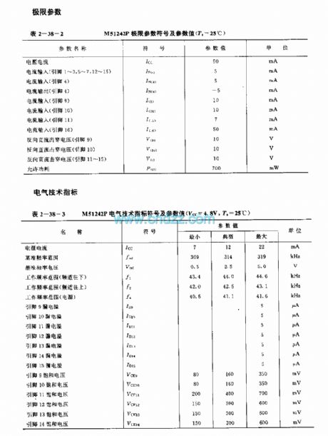
The M51242P is designed as one kind of six functions infrared remote control receiving integrated circuit that can be used in the TV set and the audio equipment applications. The internal circuit is composed of the input frequency counter, the decode counter, the pulse control circuit, the latch circuit, the coincidence circuit and the decoding circuit.
Features
It has stable frequency standard and low frequency distortion;Open collector output;The circuit has the Zener voltage stabilization diode;16-pin dual-row DIP package.
(View)
View full Circuit Diagram | Comments | Reading(890)
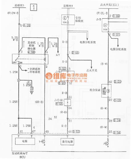
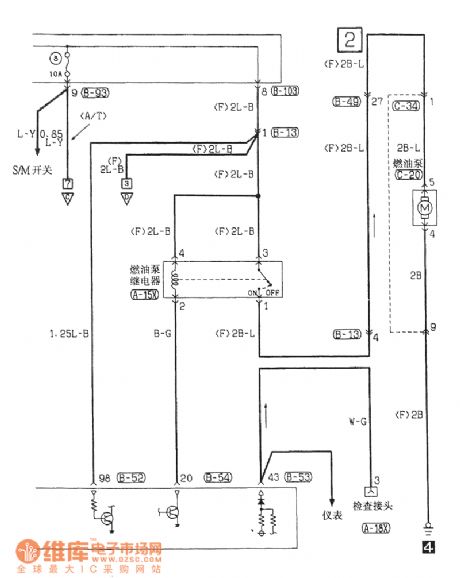
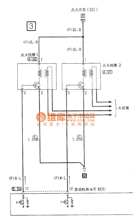
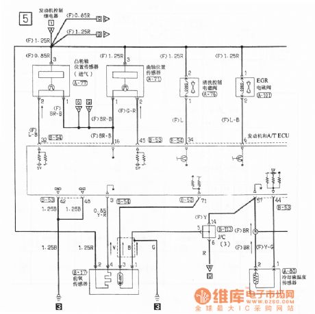
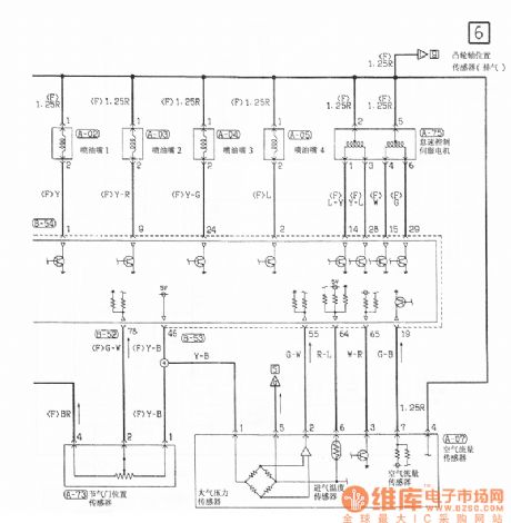
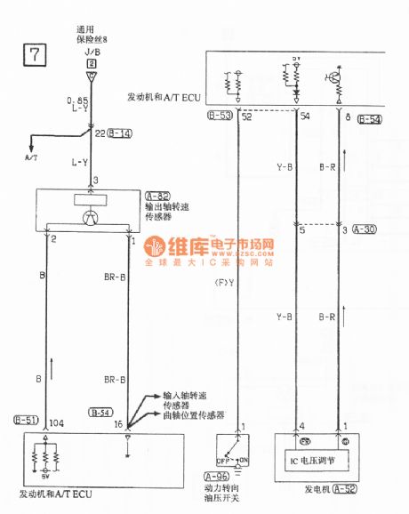
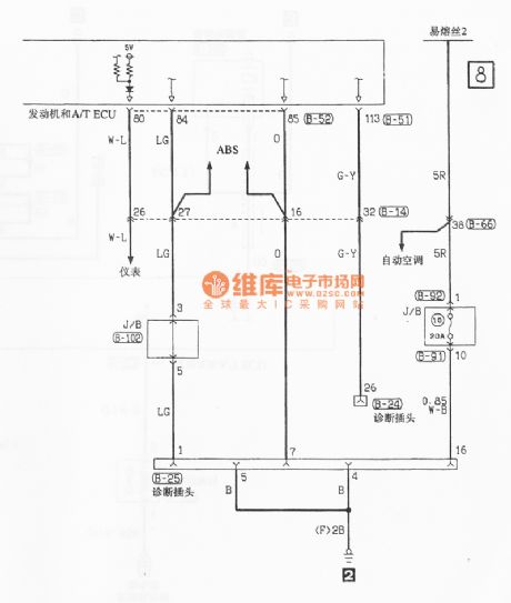
Southeast Soveran motor control circuit
Published:2011/7/12 9:36:00 Author:John | Keyword: motor


View full Circuit Diagram | Comments | Reading(820)
M58481P (TV and audio equipment) 30 functions infrared remote control receiving circuit
Published:2011/7/13 6:59:00 Author:Christina | Keyword: TV, audio equipment, 30 functions, infrared remote control, receiving circuit
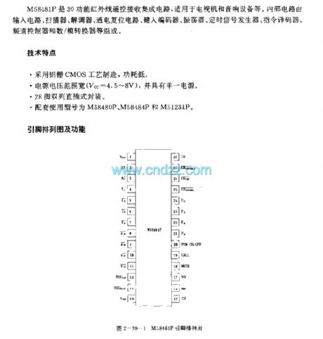
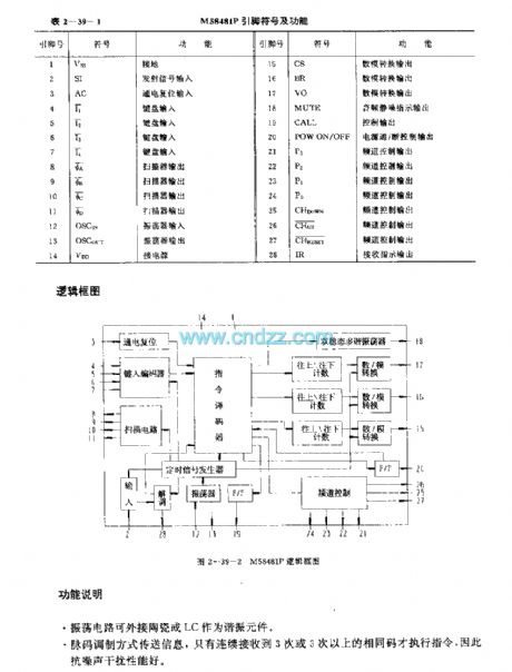
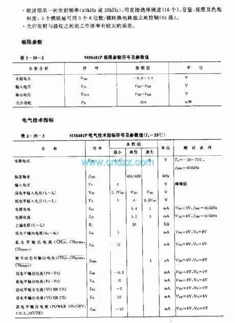
The M58481P is designed as one kind of 30 functions infrared remote control receiving circuit, and it can be used in the TV and audio equipment applications. The internal circuit is composed of the input circuit, the scanner, the modem, the power-on reset circuit, the type encoder, the oscillator, timing signal generator, instruction decoder, channel controller and the D/A converter.
Features
It uses the aluminum-gate CMOS process, the power consumption is low;The voltage range of the power supply is wide, and it has the single power supply;It can be used with the M58480P,M58484P and M51231P;It is in the 22-pin dual-row DIP package;The oscillation circuit can connect with the ceramic or LC as the resonant component.
(View)
View full Circuit Diagram | Comments | Reading(842)
M51240P (TV set and the audio equipment) 6 functions infrared remote control receiving circuit
Published:2011/7/13 7:08:00 Author:Christina | Keyword: TV set, audio equipment, 6 functions, infrared remote control, receiving circuit
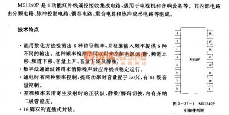
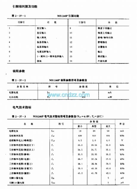

The M51240P is designed as one kind of six functions infrared remote control receiving integrated circuit that can be used in the TV set and the audio equipment applications. The internal circuit is composed of the input frequency counter, the decode counter, the pulse control circuit, the latch circuit, the coincidence circuit and the decoding circuit.
Features
You can use the digital method to test out six kinds of signal frequenciesThe digital low-pass filter can be used to eliminate the noise effect and supply the stable operation;It has two kinds of control frequencies;The circuit has the Zener voltage stabilization diode;16-pin dual-row DIP package.
(View)
View full Circuit Diagram | Comments | Reading(835)
New depolarization nickel cadmium battery automatic charger circuit
Published:2011/7/13 20:00:00 Author:TaoXi | Keyword: New, depolarization, nickel cadmium battery, automatic charger


The structure diagram of the charger is as shown in figure 4-35, the circuit principle is as shown in figure 4-36. The constant current source which is modulated by the V pulse is composed of IC2, it charges the battery. The 10-bit pulse distribution circuit is composed of the IC5A and IC6, the Co port continuously outputs the low level and high level with 5-bit width to control the cut-off and conduction of V1 and this method realizes the constant current pulse charging and stop-charging of the battery. Q1 and Q3 output the high levels with 1-bit width when the Co outputs the high level, and the 1-bit high levels trigger the battery voltage detection circuit which is composed of the IC5B and the discharging current respectively. IC4 supplies precision reference source which is needed by the 3V comparator.
(View)
View full Circuit Diagram | Comments | Reading(576)
Practical circuit of the step-down chopper type switching voltage stabilization power supply
Published:2011/7/12 0:48:00 Author:TaoXi | Keyword: Practical circuit, step-down, chopper, switching, voltage stabilization, power supply

The practical circuit of the step-down chopper type switching voltage stabilization power supply is as shown in the figure. The VT1 is the adjusting switching tube, the VT2 and VT3 are the two-stage switching tube. The VD1 and VD2 which are connected with the two promote tubes' emitters can be used to prevent the reverse breakdown of the transistor emitter junction. The conduction and cut-off time of VT1 are decided by the self-excited multivibrator which is composed of the VT5 and VT6, the VT4 emitter follower plays the isolation and amplification functions. The flip time of the multivibrator depends on the emitter-coupled differential amplifier which is composed of VT7 and VT8.
When the output voltage range of this circuit is ±20%, the input voltage range is in the range of ±0.5%, the efficiency is 93%.
(View)
View full Circuit Diagram | Comments | Reading(1575)
Polarity transform type and chopped type switching voltage stabilization power supply principle diagram
Published:2011/7/12 1:02:00 Author:TaoXi | Keyword: Polarity transform, chopped type, switching, voltage stabilization, power supply, principle diagram

The polarity transform type and chopped type switching voltage stabilization power supply principle diagram is as shown in the figure. When the switching adjustment component transistor VT is in the conduction state, the input voltage Vi adds to L to produce the current, the diode VD cuts off reversely. When the transistor VT is cutting off, the current of inductance L decreases gradually, the polarity of the induced electromotive force is as shown in the figure. This induced electromotive force conducts the diode VD to charge the capacitance C, the polarity of the output voltage Vo of the capacitance C is opposite with the input voltage Vi. When the voltage of the load will fall, the capacitance C discharges the load again. The output voltage Vo will higher than the input voltage Vi.
(View)
View full Circuit Diagram | Comments | Reading(559)
Width modulation, frequency modulation hybrid type switching power supply (1)
Published:2011/7/12 1:16:00 Author:TaoXi | Keyword: Width modulation, frequency modulation, hybrid type, switching, power supply

The self-excited oscillation of this circuit is realized by the R13C1. When the power is starting, the 220V AC adds to the primary stage of the transformer T1, and it is secondary transformed, bridge type rectified and filted by this circuit, then the capacitance C6 outputs the 15V unstable smooth DC voltage to add to the input ports of the complex switching power transistors VTl2~VT14; at the same time, this voltage supplies the stable operating voltage for the integrated voltage regulator W724 through the resistor R10 and the regulator VD6. Becasue the output voltage Vo has not established, so the two ends of the sampling voltage divider resistors R17, R24, R18 has no voltage, the VT5 of the error amplifier cuts off because there is no base electrode bias voltage.
(View)
View full Circuit Diagram | Comments | Reading(507)
| Pages:1551/2234 At 2015411542154315441545154615471548154915501551155215531554155515561557155815591560Under 20 |
Circuit Categories
power supply circuit
Amplifier Circuit
Basic Circuit
LED and Light Circuit
Sensor Circuit
Signal Processing
Electrical Equipment Circuit
Control Circuit
Remote Control Circuit
A/D-D/A Converter Circuit
Audio Circuit
Measuring and Test Circuit
Communication Circuit
Computer-Related Circuit
555 Circuit
Automotive Circuit
Repairing Circuit