power supply circuit
Practical circuit of the step-down chopper type switching voltage stabilization power supply
Published:2011/7/12 0:48:00 Author:TaoXi | Keyword: Practical circuit, step-down, chopper, switching, voltage stabilization, power supply | From:SeekIC
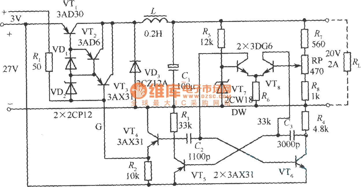
The practical circuit of the step-down chopper type switching voltage stabilization power supply is as shown in the figure. The VT1 is the adjusting switching tube, the VT2 and VT3 are the two-stage switching tube. The VD1 and VD2 which are connected with the two promote tubes' emitters can be used to prevent the reverse breakdown of the transistor emitter junction. The conduction and cut-off time of VT1 are decided by the self-excited multivibrator which is composed of the VT5 and VT6, the VT4 emitter follower plays the isolation and amplification functions. The flip time of the multivibrator depends on the emitter-coupled differential amplifier which is composed of VT7 and VT8.
When the output voltage range of this circuit is ±20%, the input voltage range is in the range of ±0.5%, the efficiency is 93%.
Reprinted Url Of This Article:
http://www.seekic.com/circuit_diagram/Power_Supply_Circuit/Practical_circuit_of_the_step_down_chopper_type_switching_voltage_stabilization_power_supply.html
Print this Page | Comments | Reading(3)

Article Categories
power supply circuit
Amplifier Circuit
Basic Circuit
LED and Light Circuit
Sensor Circuit
Signal Processing
Electrical Equipment Circuit
Control Circuit
Remote Control Circuit
A/D-D/A Converter Circuit
Audio Circuit
Measuring and Test Circuit
Communication Circuit
Computer-Related Circuit
555 Circuit
Automotive Circuit
Repairing Circuit
Code: