
Circuit Diagram
Index 1550
KA22427--the AM tuning/FM INTREQ radio integrated circuit
Published:2011/7/12 2:32:00 Author:Borg | Keyword: INTREQ, radio, integrated circuit
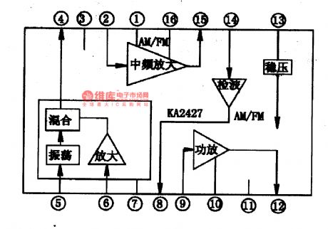


1.the internal circuit and pin functions of KA22427 The AM part of KA22427 includes all the circuit between AM aerial input and detection output; the FM part doesn't include the high frequency amplifier and mix, but only includes the circuit between FM intermediate frequency and discrimination output. Besides, the integrated circuit also contains the power amplifier circuit. Therefore, only one more FM high frequency head can make KA22427 a whole FM/AM radio.The internal circuit of KA22427 is shown in figure 1-1, and this IC is in the 16-pin dual in-line package.
(View)
View full Circuit Diagram | Comments | Reading(9842)
KA22234-the double 5-stage balance power integrated circuit
Published:2011/7/12 3:46:00 Author:Borg | Keyword: 5-stage, balance power, integrated circuit
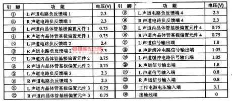
KA22234 is a double 5-stage balance power integrated circuit produced by Samsung, Korea, which is widely used in all types of stereo equipment to regulate the tone quality of the 2-lines of stereo signals.KA22234 contains 2 lines of 5-stage balance power integrated control circuits with the same functions, it is in 24-pin dual in-line plastic structure package, and its pin functions and data are listed in table 1-1.
Table 1-1 the pin functions and data of KA22234
(View)
View full Circuit Diagram | Comments | Reading(721)
KA22135-the single chip stereo playback integrated circuit
Published:2011/7/12 2:20:00 Author:Borg | Keyword: single chip, stereo playback, integrated circuit


KA22135 is a single chip stereo playback integrated circuit produced by Samsung, which is used in all kinds of ultra-small radios and recorders. 1.the internal circuit and pin functions of KA22135 KA22135 contains two lines of preset amplifier circuit, power amplifier circuit and motor speed control circuit of the same function. The internal circuit and typical application circuit is shown in figure 1-1. The IC is in the flat 22-pin dual line package, and its pin functions and data are listed in table 1-1.
(View)
View full Circuit Diagram | Comments | Reading(852)
The ground circuit of Santana 2000(gasoline injection engine)
Published:2011/7/12 20:17:00 Author:Borg | Keyword: ground circuit, gasoline injection engine
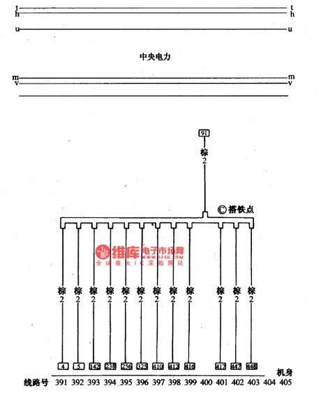
figure: The ground circuit of Santana 2000(gasoline injection engine) (View)
View full Circuit Diagram | Comments | Reading(459)
The main parameters of the AC generator
Published:2011/7/11 21:13:00 Author:Borg | Keyword: main parameters, AC generator
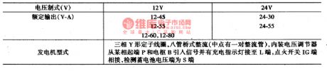
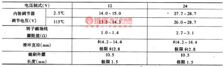
AC generatorThe main parameters of the AC generator are shown in figure 3, the structure of the AC motor is shown in Figure 1.
(View)
View full Circuit Diagram | Comments | Reading(805)
The main technology parameters of the battery
Published:2011/7/11 21:28:00 Author:Borg | Keyword: technology parameters, battery
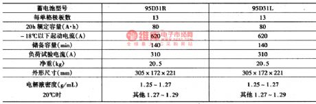
(2) the main features of the power supply starting system1.batteryThe main technology parameters of the battery are shown in figure 2.
(View)
View full Circuit Diagram | Comments | Reading(751)
The CXA1033P AM single chip radio integrated circuit
Published:2011/7/11 21:39:00 Author:Borg | Keyword: single chip, integrated circuit
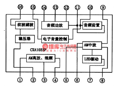

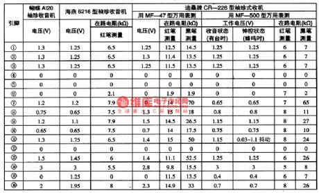
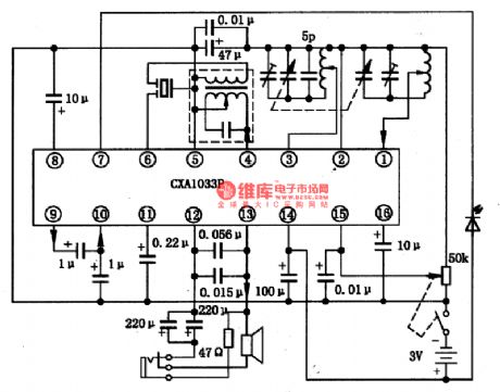
CXA1033P is an AM single chip radio circuit which is produced by Sony, which is used in the low-voltage radio and recorder. 1.the internal circuit and pin functions of CXA1033P CXA1033P includes the AGC, mix, INTREQ, detection, LED drive and audio pre-stage, audio power amplifier, etc. The internal circuit of the integrated chip is shown is figure 1. The IC is in 16-pin dual in-line package, whose pin functions and data are shown in figure 1, in figure 2 is the tested data of several radios composed of CXA1033P.
(View)
View full Circuit Diagram | Comments | Reading(2816)
The the main tech parameters of the diesel engine
Published:2011/7/11 21:54:00 Author:Borg | Keyword: tech parameters, diesel engine
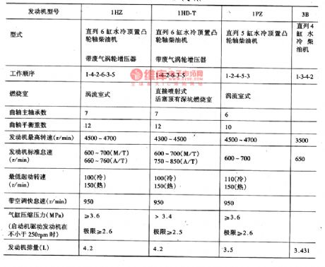

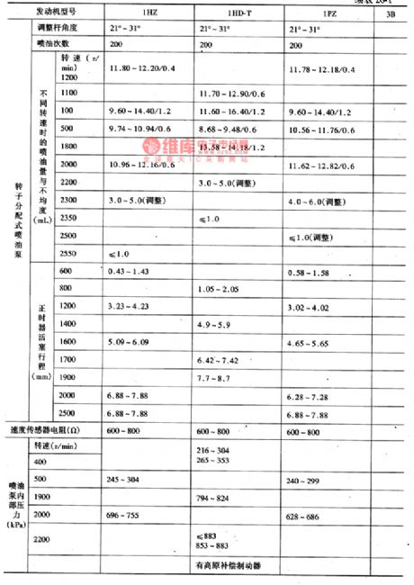
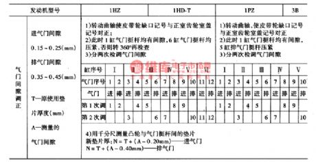
The medium-sized bus of Coster (or Cruise) produced by Toyota takes a large share of Chinese market, of which the ones imported in 80s are gasoline cars, such as RB10, RB11 and BB1O; and the ones imported in 90s are almost diesel cars, such as PZJ(HZJ)70/73/75,HDJ80, HZB30 and HDB30. (1) the main parameters of the engineThe Coster are installed with the 1PZ 5-cylinder diesel engine or 1HZ and 1HD-T 6-cylinder engine, the main parameters are shown in figure 1.
(View)
View full Circuit Diagram | Comments | Reading(921)
The CXA1O19 AM single chip radio integrated circuit
Published:2011/7/11 22:10:00 Author:Borg | Keyword: single chip radio, integrated circuit


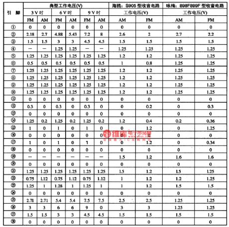
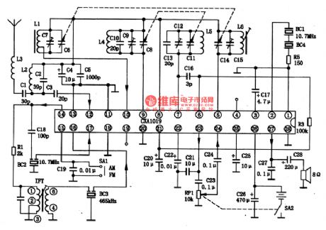

2. The internal circuit and pin functions of CXA1O19CXA1O19 is in 28-pin dual line plastic structure, whose internal circuit is shown in figure 1, and the pin function of the integrated circuit is shown in table 1. In table 21 are the typical static voltages when IC is at 3V, 6V and 9V and in AM or FM state respectively (in the table also lists the tested data of 2 models).
Figure 1 the internal circuit of CXA1O19
Table 1 the pin functions of the CXA1O19 single chip integrated circuit
Table 2 the tested data of the the CXA1O19 single chip integrated circuit
(View)
View full Circuit Diagram | Comments | Reading(1582)
The illustration of the manifold meter--the pressure circuit of high and low pressure pipe
Published:2011/7/11 22:25:00 Author:Borg | Keyword: manifold meter, low pressure
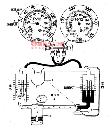
(1) cooling systemClose the 2 hand stop valve of the manifold pressure meter, connect the high pressure(red) and the low pressure(green) pipe with the according filler openings respectively, the yellow filler pipe is connected with the pump entrance, start the pump, then open the valves, when the low pressure meter indication is lower than -0.O9MPa(-740mmHg pillar), it means the pump should run for 10m more, then close the valves and keep the state for 30m, if the low pressure meter is not coming back, it mean the system has not leakage, so it can be filled with R-12, or the leakage spot should be tested.
(View)
View full Circuit Diagram | Comments | Reading(494)
The manifold pressure meter circuit
Published:2011/7/11 22:38:00 Author:Borg | Keyword: manifold pressure meter
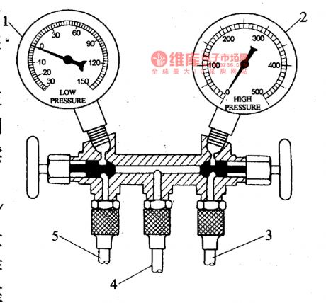
Before we add the coolant into the air-conditioner system, the air and water in it should be strained out, and the content should be controlled, or it will cause accidents. To test the vacuum degree of the air-conditioning system and the pressure after the coolant is added, we can use the manifold pressure meter and vacuum pump, etc. There is a multi-channel valve seat on the manifold pressure meter, and the low and high pressure meter on the seat, the low voltage is used to display the pressure on the low voltage side of the cooling system.
(View)
View full Circuit Diagram | Comments | Reading(748)
The diagram reading illustration of DPCA-Fukang DC7140
Published:2011/7/11 23:11:00 Author:Borg | Keyword: illustration, DPCA-Fukang

Figure: The diagram reading illustration of DPCA-Fukang DC7140 (1) the two letters on the two side of the wire indicate the symbols of the wire bundles, the figured T1B means the wire is in TB wire bundle, other bundles, such as PB, MT, AV, CP, FR and MV, all the them are the names of the car wire. (2) the wire colors are represented by the letters and the transverse lines near the connector, of which the letters with lines on them means basic color, the other letter means the stripe color on the wire, which are the differences. (View)
View full Circuit Diagram | Comments | Reading(530)
The MPEG-2 and AC-3 decoding integrated circuit of L64021 single chip LS1
Published:2011/7/12 0:13:00 Author:Borg | Keyword: decoding, integrated circuit


L64021 is a MPEG-2 single chip AV decoding integrated circuit produced by LSILOGIC, which combines the MPEG-2 and AC-3 decoder of LSI and CSS copyright protection circuit, it is a mass MPEG-2 decoding integrated circuit. It is compatible with VDC and CD-ROM form, and it is widely used in DVD players and multimedia PC, such as SONY DVD players, etc. 1.the functions of L64021 internal circuit In figure 1-1 is the internal structure principle circuit of L64021, which consists of the main CPU connection circuit, data channel connector circuit and so on.
(View)
View full Circuit Diagram | Comments | Reading(817)
The Shanghai air-conditioning system circuit in Nanjing Iveco A40.10 light car
Published:2011/7/12 0:36:00 Author:Borg | Keyword: air-conditioning system, Nanjing Iveco
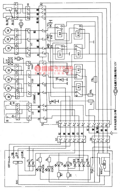

(6) The Shanghai air-conditioning system circuit in Nanjing Iveco A40.10 light car In the KQZN101 air-conditioning system of A40.10 light car (see as figure 26), there are 4 axis flowing condensers, which are M1, M2, M3 and M4, 3 evaporators of M5, M6 and M7 (2-axis centrifugal), there is also the wind switch SA1 on the dashboard, LED indicator, alarm lamp, temperature switch WKQ and hand control switch SA2. To read it more conveniently, figure 26 is simplified as figure 27. When the switch SA1 is closed, the temperature controller WKQ is getting into working.
(View)
View full Circuit Diagram | Comments | Reading(536)
The Shanghai air-conditioning system circuit of Nanjing Iveco A40.10 light car (middle-roof)
Published:2011/7/12 0:48:00 Author:Borg | Keyword: air-conditioning system, light car
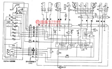
(5)The Shanghai air-conditioning system circuit of Nanjing Iveco A40.10 light car (middle-roof) (see as figure 25)The car is controlled by the KQSN6-4Ⅰelectric control system. On the dashboard, there is the wind volume switch SA1, temperature switches KQ and SA2, power supply indicator POWER cooling indicator COOL, the high voltage indicator HP and lower voltage fault indicator LP. The wind volume switch power is from the connection terminal G9 in the central box of the car, which is under the control of 15/A pillar, and the power supply of other motors andcompressors is the battery positive pole (DC12V) which connects with all the contactor of all the relays.
(View)
View full Circuit Diagram | Comments | Reading(1274)
The fuse circuit of DPCA-Fukang DC7140 car
Published:2011/7/12 0:50:00 Author:Borg | Keyword: fuse circuit, DPCA-Fukang

figure: The fuse circuit of DPCA-Fukang DC7140 car (View)
View full Circuit Diagram | Comments | Reading(504)
Minitype lead-acid storage battery adjustable charger circuit
Published:2011/7/13 21:19:00 Author:TaoXi | Keyword: Minitype, lead-acid, storage battery, adjustable charger

Operating principle:
The circuit is as shown in the figure 3-8. This circuit is composed of the charging control circuit, the sample comparison amplifier circuit, the automatic shutdown circuit.
The charging control circuit: the 220V city electricity is transmitted into the transformer T1 through the switching component S1, and the transformer secondary stage outputs the 18V AC voltage, this voltage is rectified by the bridge circuit which is composed of the VD1-VD4, so we get the 100Hz pulsating DC voltage.
The sample comparison amplifier circuit: the power supply is the voltage which is rectified by VD1-VD4, and it is stabilized by R2 and VD5, then it is filted by C1 to get the 12V voltage, the benchmark voltage is supplied by VD6.
(View)
View full Circuit Diagram | Comments | Reading(735)
Walkman charger circuit
Published:2011/7/13 21:35:00 Author:TaoXi | Keyword: Walkman, charger

View full Circuit Diagram | Comments | Reading(920)
Four-channel single battery independent charging automatic charger circuit
Published:2011/7/13 21:54:00 Author:TaoXi | Keyword: Four-channel, single battery, independent charging, automatic charger

The feature of this charger is that it can independently charge the four-channel single battery, each channel has a automatic control charging circuit, and four red LEDs indicate the charging status respectively.
The city electricity is reduced by the transformer T, one channel is rectified by VD1, then it is filted by R1 and C1, stabilized by VD4 to output the 4.6V stable voltage through the R2, C2 secondary filter, this voltage is used by four channels of control circuit; another channel is rectified by VD2 to supply the four channels of half-wave pulse current for the charging. In the figure there is only one channel of control circuit, the other channels are the same. The control manifold uses the quad comparator LM339.
(View)
View full Circuit Diagram | Comments | Reading(666)
Automatic charging, power supply dual-use device circuit (1)
Published:2011/7/14 2:07:00 Author:TaoXi | Keyword: Automatic, charging, power supply, dual-use, device

The automatic charging, power supply dual-use device circuit is as shown in the figure 4-2. IC1 is the three-port voltage stabilizer LM317T, it forms the adjustable voltage stabilization power supply, the output voltage can be adjusted in the range of 1.25V-20V through RP1; IC2 is the CD4060, it is designed as one kind of 14-stage binary addition calculator/oscillator, the timer and pulse generator is composed of this calculator/oscillator and the external components. IC3 is the NE555, it forms the simple automatic charging circuit; IC4 is the sampling controller that is composed of the four-two input NAND gate CD4011 to control the conversion of the charging current.
After the battery is installed, it gives a positive pulse to the pin-12 of IC2 through C6, the IC2 starts to oscillate, the oscillation frequency is about 1.8Hz that is decided by the R6 and R7.
(View)
View full Circuit Diagram | Comments | Reading(762)
| Pages:1550/2234 At 2015411542154315441545154615471548154915501551155215531554155515561557155815591560Under 20 |
Circuit Categories
power supply circuit
Amplifier Circuit
Basic Circuit
LED and Light Circuit
Sensor Circuit
Signal Processing
Electrical Equipment Circuit
Control Circuit
Remote Control Circuit
A/D-D/A Converter Circuit
Audio Circuit
Measuring and Test Circuit
Communication Circuit
Computer-Related Circuit
555 Circuit
Automotive Circuit
Repairing Circuit