
Circuit Diagram
Index 1560
water level automatic control circuit consisting of 555
Published:2011/7/8 2:28:00 Author:Fiona | Keyword: water level automatic control

As shown in figure is water level automatic control circuit. The control circuit is composed of step-down rectifier circuit,water level measurement and control switch,flip and flop generator and so on.Step-down rectifier circuit provides VDD = 12 V power supply voltage for 555.Two steady state work patterns of 555 is used as RS trigger. BG1 and upper limit water level probe A are reset trigger switch; BG2 and the median probe B are setting trigger switch; C is the lower limit probe connecting to the ground electrical level. Using the characteristics of RS trigger and controlling the setting and resetting of 555 make the relay J absorb or release , so as to control the operation of the pumping motor D to make water level keep in the given upper limit and lower limit.
(View)
View full Circuit Diagram | Comments | Reading(1766)
Long Time Timing Circuit
Published:2011/7/9 2:14:00 Author:Joyce | Keyword: Long Time , Timing
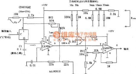
As shown in the figure is a long time timing circuit. This circuit uses the discharging mode of controllable operation amplifier CA3094 to get long time timing. In order to change the fixed time continuously, it is usually achieved by changing VH through RV1.
(View)
View full Circuit Diagram | Comments | Reading(818)
TWH8778 radio automatic shutdown circuit
Published:2011/7/7 7:09:00 Author:Fiona | Keyword: radio automatic shutdown, sound signal

The circuit mainly uses a new type of power switching device TWH8778.It produces simply and has no debugging.TWH8778 shape and the function of the pins is shown as above,the ⑤ pin is control side,when the pin's voltage is higher than the cut-in voltage (about 1.6V), the electronic switch is closed, ①, ② pins are connected. When touching the contact of the touch switch between BG1 and the power,BG1 is conducted,the voltage drop of R1 makes TWH8778 close,the recorder works normally due to the power is connected.If the recorder is on playback, thesound signal is coupled by C3 to the base of BG3 to make BG2 conduct,BG2 has a base current and it is in the conduction state,the voltage drop of R1 makes TWH8778 close again. (View)
View full Circuit Diagram | Comments | Reading(773)
A bean sprouts automatic watering controller consisting of 555 circuit
Published:2011/7/8 2:20:00 Author:Fiona | Keyword: automatic watering controller

Figure shows the bean sprouts automatic watering control circuit. The controller consists of step-down rectifier circuit, power outage told implement (IC3), timing control circuit (IC1), temperature control circuit(IC2) and so on. The step-down rectifier circuit is VDD = +7 V DC voltage provided by the whole controller. The power outage told implement is controlled by many harmonic oscillator which consists of IC3,R3,R4,C5 and other components. Close the switch K1, when the power cuts, the relay J1 releases, contact J1-1 closes, IC3 starts oscillation due to get electricity, the oscillation frequency is about 1000Hz, the output signal drives the speaker sound to inform the owner that the power goes out. (View)
View full Circuit Diagram | Comments | Reading(1183)
CIC38 Series Music Integrated Circuit
Published:2011/7/8 9:08:00 Author:Joyce | Keyword: CIC38 Series, Music , Integrated


CIC38 series music integrated circuit can directly drive the piezoelectric ceramics buzzer, as shown in figure (a). When the power supply voltage VDD is 3V, it can promote the piezoelectric ceramic buzzer and the light-emitting diodes at the same time, the application circuit is as shown in figure (b). If you want to get a larger volume, you can connect an amplifier transistor V T1 (9013 or 8050) externally to drive the horn, the specific circuit is as shown in figure(c).
Names of songs stored in the CIC38 series integrated circuit:
(View)
View full Circuit Diagram | Comments | Reading(643)
the wind speed program control circuit consisting of 555
Published:2011/7/8 2:25:00 Author:Fiona | Keyword: the wind speed program control

Just when turning on the power,the start-up circuit consisting of R1,C1 and BG1 produces a negative pulse and adds to the trigger of IC1 (555) (② pin), so that the delay circuit consisting of IC1, W1, R3, C3 is set and outputs the high level. The corresponding delay time is td1 = 1.1 (Rw1 + R3) C3, the parameters of the corresponding time is about 0.6 to 10 seconds. During this time, C3 is charged, when the voltage of C3 is filling to make the ⑥ pin reach 2/3VDD, IC1 is reset,after low level output by 3-pin differentials through the C4, R5,it adds to ② pin of IC2 to make the corresponding timing circuit is set and outputs high levelbecause that the ② pin is low level. IC3, IC4's change of state is similar.
(View)
View full Circuit Diagram | Comments | Reading(518)
FM/AM Monolithic Radio Circuit
Published:2011/7/9 2:47:00 Author:Joyce | Keyword: FM/AM, Monolithic , Radio

As shown in the figure is a TA7781P/7781F FM/AM monolithic radio circuit. (View)
View full Circuit Diagram | Comments | Reading(1158)
Precise Digital Timing Controller Circuit
Published:2011/7/9 2:31:00 Author:Joyce | Keyword: Precise , Digital , Timing , Controller
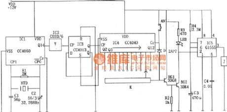
As shown in the figure is a precise digital timing controller circuit, which is composed of a crystal oscillator circuit, a frequency divider, a counting circuit and a monostable trigger.
The crystal oscillator circuit constitutes of a 14 bit binary serial count/distributor, a clock crystal (32768 Hz), C1, C2 etc.The crystal signal will be output through feet③(Q14) after being divided 214 times .Then it will be inverted by IC2 and then divided by double D flip-flop CC4013 (IC3) to be a signal of 1 Hz. The signal will be added to the CP end of IC4 as the control signal of the clock.
IC4 is a 12 bit binary serial count/distributor CC4040, when the signal frequency of CP is 1 Hz ac, the 11 output ends Q4 ~Q9, Q12 ~ Q14 are to output pulse(phase step high level) of 2 seconds, 4 seconds, 8 seconds, 16 seconds, 32 seconds, 64 seconds, 128 seconds, 256 seconds, 512 seconds, 1024 seconds, 2048 seconds respectively. (View)
View full Circuit Diagram | Comments | Reading(1037)
a TV set automatic shutdown control circuit consisting of 555
Published:2011/7/8 2:18:00 Author:Fiona | Keyword: automatic shutdown control

When there is a television program,the sync signal from point A makes BG1 saturated conduct,BG2, BG3 conducts, so that 555 is set due to thepin ② is low level, the high level output by ③ feet makes JB put together, J1 is closed and the TV power supply connects up; when the television program is aired, synchronous signal disappears, BG1, BG2 end.C2 which has been charged discharges through the emitter of R5, BG3 and makesBG3 stay about 10 minutes conducting timeto avoid the undue off phenomenon caused by intermittent or replacement when program broadcasts. (View)
View full Circuit Diagram | Comments | Reading(623)
consisting of 555 no tower pressurization supply water liquid level control circuit
Published:2011/7/8 2:33:00 Author:Fiona | Keyword: no tower pressurization, supply water, liquid level control

The control circuit consists of capacitance step-down rectifier circuit,electro connecting pressure gauge,555 trigger circuit,SCR control circuit. Capacitance step-down rectifier circuit provides DC voltage for the whole control circuit.When there is no water in the water control, the electro connecting pressure gauge P's internal pressure is low,the movable contact l in table and lower contact 3 are closed,so that IC (555) ② pin is low level,the corresponding 555 is set,the high level output by 3-pin makes the semiconductor control rectifier SCR trigger conduct,CJ pulls in, pump D fetches water inside the water control,the pressure in the pressure gauge increases. (View)
View full Circuit Diagram | Comments | Reading(1031)
Music Integrated Circuit
Published:2011/7/8 8:48:00 Author:Joyce | Keyword: Music , Integrated

CIC481 is a CMOS music integrated circuit with songs played by piano, organ and mandolin. It can be used in products like toys, clocks, doorbells, etc. Its typical application circuit is as shown in the figure.
(View)
View full Circuit Diagram | Comments | Reading(1110)
MEMS stroboscopic drive circuit
Published:2011/7/1 5:39:00 Author:Fiona | Keyword: MEMS stroboscopic drive

According tostroboscopic imaging principle,in order to collect the clear images of MEMS devices high-speed movement,this paper selects EL6249C as the drive chip to drive the high brightness laser diode to shine,and uses the narrow pulse signal with the same frequency as the function generator frequency and MEMS exercise frequency,meanwhile,it is used as the control signal for EL6249C,then sets the right external resistance to make EL6249C output appropriate electricity to drive LED to emit the required frequency light. The graph is the author of the design stroboscopic lighting circuit principle diagram. In this circuit, in order to ensure the required supply voltage is stable at 5V, the writer uses the MAX8869, so it can improve the accuracy and stability of the entire circuit.
(View)
View full Circuit Diagram | Comments | Reading(503)
Humidity measurement circuit with temperature compensation
Published:2011/7/1 5:47:00 Author:Fiona | Keyword: Humidity measurement, temperature compensation

In the actual application,it needs to consider linear processing and temperature compensationfor humidity sensor,and often uses operation amplifier to constitute humidity measurement circuit.The figure is the humidity measurement circuit.Rt is thermosensitive resistor (20kΩ, B = 4100K); RH is the H204C humidity sensor,operational amplifier type is LM2904.Humidity voltage characteristics and temperature characteristic of the circuit demonstrate that: in (30% ~ 90%) RH, 15 ℃ ~ 35 ℃ range,the humidity errorexpressed bythe output voltage is less than 3% RH. (View)
View full Circuit Diagram | Comments | Reading(1311)
LED producing rapid pulse light circuit
Published:2011/7/1 5:50:00 Author:Fiona | Keyword: LED, producing rapid pulse light
Only using two integrated circuits can help reduce size and power consumption (Figure 1).Normal high level pulse output by output gate G4 in the IC2 has about 2.5ns rise and fall time,and less than 10 ns pulse width, which is equivalent to three gate delays.These pulses are very suitable for pulling low the cathode potential of HLMP-CB-15-speed blue LED,and the LED anode is clamped to 5V G4 compels almost the entire 5V supply voltage to be added to the LED,so large voltage swing can ensure the LED which is welded in the edge of a small printed circuit board has the best brightness. (View)
View full Circuit Diagram | Comments | Reading(532)
Timed trigger switch circuit
Published:2011/7/1 5:51:00 Author:Fiona | Keyword: timed, trigger switch

The AC power source reduces the voltage by the capacitance C1,bridge rectifies by diode vDl—vD4,filters by the capacitor C2 and obtains the 12V DC voltage in both ends of the diode VD5.After rectifying and current-limiting by the diode vD6 and resistor R2,the supply voltage charges the capacitor c4 by potentiometer RP, and resistors R3, R4.When the voltage of the A's ② ⑥ pins is greater than 2 / 3 supply voltage because of c4 both ends voltage being charged to time base integrated circuit, A is in reset state, its ③ pin is low,the relay KM is closed to make the moving contacts are launched to control the trigger circuit or lanterns.
(View)
View full Circuit Diagram | Comments | Reading(636)
Internal telephone circuit
Published:2011/7/1 5:53:00 Author:Fiona | Keyword: Internal telephone

Internal telephone circuit is shown as below,improving slightly a toy telephone will become a variable practical internal telephone. This phone is compose of the phone component,decoding circuit,ringing circuit and other components. Using more than two the same device parameters telephone connected by wire can constitute internal telephone.
(View)
View full Circuit Diagram | Comments | Reading(2111)
New smart phone manager circuit
Published:2011/7/8 1:13:00 Author:Fiona | Keyword: New smart phone, manager

New smart phone manager circuit is shown as above,this device uses specific intelligent communications integrated controller chip ZH988A for the communications for the core to compose the smart phone manger, the circuit is shown as below. Its main functions are: 1 every phone can beset up19 users, the user has independent password and account, it achieves household management;2 limit each of user to do permissions, costs plan and so on; 3 open 110,119,114 and other free items; 4 automatically calculate the holding time and cost; 5 the data and passwords can be modified by keyboard;6 securitybeat monitoring;7 P / T is compatible and so on.
(View)
View full Circuit Diagram | Comments | Reading(1621)
interface circuit of power line carrier chip PM2300 and 89C2051
Published:2011/7/5 5:30:00 Author:Fiona | Keyword: power line carrier chip, interface

PM2300 is single power line carrier chip and 12 pin single in-line package thick-film integrated circuit for packaging the SSC P300 which is produced by Intellon company and analog circuit relative to power interface together.It has SPI synchronous serial interface.
(View)
View full Circuit Diagram | Comments | Reading(1966)
the interface circuit composed of RS232
Published:2011/7/5 5:30:00 Author:Fiona | Keyword: interface circuit

View full Circuit Diagram | Comments | Reading(552)
FT2232C and RS-422 conversion circuit
Published:2011/7/7 0:02:00 Author:Fiona | Keyword: conversion

View full Circuit Diagram | Comments | Reading(616)
| Pages:1560/2234 At 2015411542154315441545154615471548154915501551155215531554155515561557155815591560Under 20 |
Circuit Categories
power supply circuit
Amplifier Circuit
Basic Circuit
LED and Light Circuit
Sensor Circuit
Signal Processing
Electrical Equipment Circuit
Control Circuit
Remote Control Circuit
A/D-D/A Converter Circuit
Audio Circuit
Measuring and Test Circuit
Communication Circuit
Computer-Related Circuit
555 Circuit
Automotive Circuit
Repairing Circuit