Remote Control Circuit
Precise Digital Timing Controller Circuit
Published:2011/7/9 2:31:00 Author:Joyce | Keyword: Precise , Digital , Timing , Controller | From:SeekIC

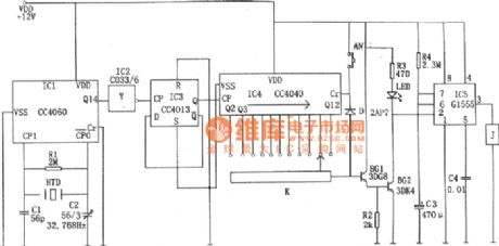
As shown in the figure is a precise digital timing controller circuit, which is composed of a crystal oscillator circuit, a frequency divider, a counting circuit and a monostable trigger.
The crystal oscillator circuit constitutes of a 14 bit binary serial count/distributor, a clock crystal (32768 Hz), C1, C2 etc.The crystal signal will be output through feet③(Q14) after being divided 214 times .Then it will be inverted by IC2 and then divided by double D flip-flop CC4013 (IC3) to be a signal of 1 Hz. The signal will be added to the CP end of IC4 as the control signal of the clock.
IC4 is a 12 bit binary serial count/distributor CC4040, when the signal frequency of CP is 1 Hz ac, the 11 output ends Q4 ~Q9, Q12 ~ Q14 are to output pulse(phase step high level) of 2 seconds, 4 seconds, 8 seconds, 16 seconds, 32 seconds, 64 seconds, 128 seconds, 256 seconds, 512 seconds, 1024 seconds, 2048 seconds respectively.
Reprinted Url Of This Article:
http://www.seekic.com/circuit_diagram/Remote_Control_Circuit/Precise_Digital_Timing_Controller_Circuit.html
Print this Page | Comments | Reading(3)

Article Categories
power supply circuit
Amplifier Circuit
Basic Circuit
LED and Light Circuit
Sensor Circuit
Signal Processing
Electrical Equipment Circuit
Control Circuit
Remote Control Circuit
A/D-D/A Converter Circuit
Audio Circuit
Measuring and Test Circuit
Communication Circuit
Computer-Related Circuit
555 Circuit
Automotive Circuit
Repairing Circuit
Code: