
Circuit Diagram
Index 1561
The switching solenoid driver circuit
Published:2011/7/8 3:18:00 Author:Fiona | Keyword: switching solenoid

The picture shows the switching solenoid driver circuit,the device U8 is 74123 chip, the device 02,03 are solid-state relays,coil PUSH is the switching inhaled coil,HOLD's ability is to maintain the coil,the power supply VDD is 24V.When the switching mechanism converts to dual fuel conversion mechanism working condition,Y1 input from 74123's B pin jumps from low to high.This change will make 74123's the output end Q input a transient high current pulse,the maintain time is ΔT.After the inverter 7404,the potential UA of A-point will appear the same width of pulse low level,the input of solid-state relay 02 has ΔT time current passed,when the output of the solid-state relay 02 has ΔT time conduction.
(View)
View full Circuit Diagram | Comments | Reading(1755)
Electric firebug circuit
Published:2011/7/10 23:41:00 Author:leo | Keyword: firebug circuit

As it is known to all, the brightness of firebug can only be seen clearly at night, which is because its brightness is not the same as that of the twinkling color lamps. The brightness of the color lamps is monotonic but that of the firebug is changing from strong to weak and its short-lived and super bright. This circuit is designed based on the emitting principle of firebug. NE555, R1, W2, C1, C2 form the multivibrator while RG, W1 and VT form light activated circuit. Mimic bus is made up of LED1, LED2, VD1, VD2, C3 and C4. (View)
View full Circuit Diagram | Comments | Reading(707)
Waveform generator made by single chip
Published:2011/7/10 23:26:00 Author:leo | Keyword: Waveform generator, single chip

As the picture shows, it is a waveform generator made by MCS-51 single chip. It has the features of simple circuit, compact construction and low price. It can produce triangle waveform, sawtooth waveform, sine waveform, square waveform and others. These six kinds of waveform can be connected to each other and constant cyclically output or be one of them can be selected out to output constantly. If key controller and LED displayer are set to it, the square wave output frequency can be set and shown by changing the software. (View)
View full Circuit Diagram | Comments | Reading(751)
Shared RF and base oscillator
Published:2011/7/10 23:16:00 Author:leo | Keyword: Shared RF, shared base

The picture shows a simple oscillator with high stability. It can start automatically with the work voltage of 12 V and work current of 1mA. Its drive circuit is D type amplifier with low output resistance and high output amplitude. Its work voltage coverage is from 2 V to 24 V and it also has other excellent features. Oscillator frequency is decided by LI and CI. As the picture shows, when the frequency of the selected component is 160kHz, time constant RI and CI will be longer than oscillating period. (View)
View full Circuit Diagram | Comments | Reading(882)
The fire damper auto control circuit of the air-conditioner
Published:2011/7/7 1:10:00 Author:Borg | Keyword: fire damper, control circuit, the air-conditioner

In the project that there is the requirement of ventilation and air-conditioning, there must be the fire damper in the air supply and return tube. When there's a fire, the temperature of air supply or return is rising up (about 70oC), which fuses the fuse strip of the fire damper, the damper is closed and makes the micro switch take action, so the fire alarm is ringing, the wind motor stops, see as the figure. This system has 4 fire dampers. When SA is in 90o (left 45o is pump running, right 45o is the motor running, 0 is shutting down), just press the key of starting ST. (View)
View full Circuit Diagram | Comments | Reading(2196)
Large power switch-The important tasks of transistors
Published:2011/7/7 1:08:00 Author:Borg | Keyword: power switch, transistors


1. Controlling the large power Nowadays, the power transistor can control powers of hundreds of thousands of volt, using the transistor as the switch has many virtues, which are:(1) it's easy to cut off, and it needs a few additional elements; (2) it's fast to switch, and it can work in a high frequency; (3) the withstand voltages of the available elements range from 100V to 700V. Years ago, the switching ability of the transistor is lower than 10kW. Nowadays, it can control powers of hundreds of thousands of volt.2. It directly works on the transistor power switch of the rectified 380V mains
(View)
View full Circuit Diagram | Comments | Reading(615)
Treatment for Osteoarthritis (the 1st)
Published:2011/7/7 9:43:00 Author:Felicity | Keyword: Treatment for Osteoarthritis, the 1st
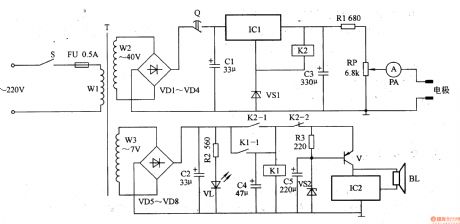
Work of the circuit
The circuit consists of power supply circuit, timing circuit, current regulation circuit, control circuit and music alarm circuit. (It is showed in the picture 9-22.)
Power supply circuit consists of power switch s, the power transformer T, rectifier diode VDl-VD8, filter capacitor Cl, an integrated three-terminal regulator ICl and voltage regulator diode VS1.
Timing circuit consists of mechanical timer Q.
Current regulation circuit consists of relay K1 and K2.
Control circuit consists of Potentiometer RP and ammeter PA.
Music alarm circuit consists of Music integrated circuit IC2, the transistor V, and the speaker BL. (View)
View full Circuit Diagram | Comments | Reading(807)
Treatment for Osteoarthritis (the 2nd)
Published:2011/7/7 9:42:00 Author:Felicity | Keyword: Treatment for Osteoarthritis, the 2nd
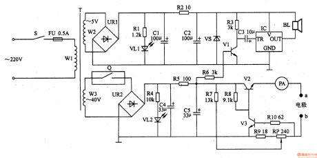
Work of the circuit
The circuit consists of power supply circuit, constant current output circuit and sound alarm circuit. (It is showed in the picture 9-23.)
Power supply circuit consists of Power switch S, fuse FU, power transformer T, Timers Q, bridge rectifier, URl, UR2, current limiting resistor Rl, R2, R4, R5, light-emitting diode VLl, VL2, filter capacitors Cl, C2, C4, C5 zener diode VS.
Constant current output circuit consists of Resistors R7-RlO, potentiometer RP, transistor V2, V3, PA meter and electrode a, b.
Sound alarm circuit consists of resistors R3, R6, capacitor C3, transistor Vl, music integrated circuit IC and speaker BL. (View)
View full Circuit Diagram | Comments | Reading(456)
light sensor application circuit diagram
Published:2011/6/18 9:56:00 Author:Nancy | Keyword: light sensor
View full Circuit Diagram | Comments | Reading(867)
UC3844 60W switching power supply circuit diagram
Published:2011/6/18 9:55:00 Author:Nancy | Keyword: 60W, switching power supply

View full Circuit Diagram | Comments | Reading(8088)
FA550O switching power supply circuit
Published:2011/7/9 3:26:00 Author:chopper | Keyword: switching, power supply circuit

Figure shows the FA550O switching power supply,its input AC voltage is 100V, output is 16V/2.5A. FA5500 is a integrated controller, its output OUT (pin ⑦) drives grid of power M0S-FET (VF1) through the resistor R2.R3 and R14are the over-current detection resistors for VF1.VF1 undertakes switch work,making the winding N1 of transformer T1 through the pulse current.C3 is the resonant capacitor, C4 is the the capacitor in order to reduce the output impedance.Theoutput voltage of winding is converted into output DC voltage after it is commutated and smoothed by VD10 and C5.
(View)
View full Circuit Diagram | Comments | Reading(994)
Small power switching power supply circuit with 5V/0.4A output
Published:2011/7/9 3:29:00 Author:chopper | Keyword: Small power, switching, power supply, 5V/0.4A output

The picture shows the small power switching power supply circuit with 5V/0.4A output.The circuit adopts saturable transformer to gain the soft switch work.
(View)
View full Circuit Diagram | Comments | Reading(3447)
MA3410 practical power supply circuit
Published:2011/7/9 3:57:00 Author:chopper | Keyword: practical, power supply circuit

MA3000 series power module is power module with part resonant power supply usage,its features are that it adopts part resonant power supply design which is similar to traditional RCC design method;and it can get a constant control when the circuit is no-load;and it can be high efficiency,low noise,and miniaturization.There is over-current protection function with soft-start function and 7-shaped drooping features; it do good to the entire module package of isolation design;and the oscillation frequency range is narrow. MA3410 practical power supply is shown as picture.
(View)
View full Circuit Diagram | Comments | Reading(901)
soft switching power supply circuit with fixed frequency
Published:2011/7/9 3:44:00 Author:chopper | Keyword: soft switching, power supply, fixed frequency

The soft switching power supply circuit with fixed frequency is shown as picture
(View)
View full Circuit Diagram | Comments | Reading(1228)
Fixed frequency common switching power supply circuit with PWM integrated controller
Published:2011/7/9 3:43:00 Author:chopper | Keyword: Fixed frequency, common, switching, power supply, PWM, integrated controller

Fixed frequency common switching power supply circuit with PWM integrated controller is shown as picture
(View)
View full Circuit Diagram | Comments | Reading(1105)
part resonant converter circuit
Published:2011/7/10 3:04:00 Author:chopper | Keyword: part, resonant converter

The frequency fr of resonant converter is fixed, it needs to change the switching frequency fs when the voltage regulates.As to practical current resonant converter,the conduction time of switch is constant, so fs must be reduced when the output voltage increases and the load is light.The sizes of transformers,reactors and other magnetic components are inverse proportional to the switching frequency, so we do not expect it to reduce. Now there is a part resonant converter,this converter solves the problem of high voltage of switching components in the voltage resonant converter.
(View)
View full Circuit Diagram | Comments | Reading(647)
LTC1148 basic application circuit
Published:2011/7/8 6:13:00 Author:chopper | Keyword: basic, application circuit

View full Circuit Diagram | Comments | Reading(510)
pin configuration and the internal equivalent circuit of LTC1148
Published:2011/7/8 20:13:00 Author:chopper | Keyword: pin configuration, internal, equivalent circuit

pin configuration and the internal equivalent circuit of LTC1148 are as shown in pictures. Pin ① (P-DRIVE) is connected to the grid of P-channel MOSFET,and when the output of this terminal is low, the high is the UI.When UI is lower than 8V,the external MOSFET sholuld use logic level threshold devices, and when UI is higher than 8V ,it should use the standard threshold devices.Pin ② (NC) is an empty pin, and it is connected to the power ground; Pin ③(UIN) is the power supply terminal.And 0.01 ~ 0.1μF ceramic bypass capacitor should be connected between pin ③ and pin @.
(View)
View full Circuit Diagram | Comments | Reading(476)
LTC1147 basic application circuit
Published:2011/7/8 20:22:00 Author:chopper | Keyword: basic, application

LTC1147 basic application circuit is shown as picture,and the input supply voltage is 5.2~14V, the output is 5V/1A.If the basic work method adoptscontinuous current mode, the MOSFET will repeat on/off,and flow through the current intermittently.This current is outputafter the smoothness of L1 and Co.Therefore, when the efficiency is 100%,the area during the conduction period of input voltage and the MOSFET is equal to the area within a period that MOSFET repeats on/off.
(View)
View full Circuit Diagram | Comments | Reading(424)
pin configuration and the internal equivalent circuit of LTC1147
Published:2011/7/8 20:31:00 Author:chopper | Keyword: pin configuration, internal, equivalent circuit

LTC1147 is mainly used for power supply circuits like DC - DC converter power of laptops and handheld computers,and also for the portable measuring instruments,battery-powered digital device,mobile phone,DC distribution system,GPS system.It has output voltages of 3.3V and 5V specifications,and can be selected based on the power supply voltage of main circuit of application system.In addition,the external P-channel MOSFET and N-channel MOSFET can expand output current,and can use LTC1148 whose efficiency is higher than LTC1147 or LTC1149/LTC1159 whose maximum input voltage is up to 48V.Thus,it can constitute a power supply circuit of high efficiency, high output current.
(View)
View full Circuit Diagram | Comments | Reading(568)
| Pages:1561/2234 At 2015611562156315641565156615671568156915701571157215731574157515761577157815791580Under 20 |
Circuit Categories
power supply circuit
Amplifier Circuit
Basic Circuit
LED and Light Circuit
Sensor Circuit
Signal Processing
Electrical Equipment Circuit
Control Circuit
Remote Control Circuit
A/D-D/A Converter Circuit
Audio Circuit
Measuring and Test Circuit
Communication Circuit
Computer-Related Circuit
555 Circuit
Automotive Circuit
Repairing Circuit