
Circuit Diagram
Index 1578
RMS / DC converter circuit for measuring AC voltage in digital multimeter
Published:2011/7/6 19:46:00 Author:Lucas | Keyword: RMS converter, DC converter measuring AC voltage converter digital multimeter

For 2V rms sinusoidal input Ui, in order to get 2V DC output voltage U. , the positive half-cycle of Al is used as a noninverting amplifier with gain work, and RR1 is used to change the gain of A1; for 2V AC RMS input voltage, RR1 transfer the output DC voltage to 2V. Rl and Cl form the low-pass filter to make the output voltage ripple small and smooth.
(View)
View full Circuit Diagram | Comments | Reading(11383)
internal equivalent circuit of HA17385 switching power supply integrated controller
Published:2011/7/10 6:17:00 Author:chopper | Keyword: internal, equivalent, switching power supply, integrated controller

HA17385 switching power supply integrated controller uses ⑧-pin DIP package,the figure shows the internal equivalent circuit.From the equivalent circuit,we can learn that HA17385 chip includes all circuits composed of switching power supply like 5V reference voltage regulator, oscillator (triangle wave generator), the error amplifier and power MOSFET drive circuit.The maximum duty ratio of PWM wave is determined by the resistor and capacitor connected to RT/CT end of oscillator.
(View)
View full Circuit Diagram | Comments | Reading(970)
CXP1103-9919EP Single-Chip Micro-Computer Integrated Circuit
Published:2011/7/9 8:25:00 Author:Robert | Keyword: Single-Chip, Micro-Computer, Integrated


The CXP1103-9919E is a single-chip micro-computer IC which is widely used in the Konka series digital color TV sets.
1.Its functional features.
The CXP1103-9919E IC's internal part is mainly made up of central processing unit (CPU), clock oscillation circuit (main clock, screen display clock), reset circuit, remote-control command signal processing circuit, I2C bus control circuit, standby/starting control circuit, screen display character generating and processing circuit, sound system control circuit, squelch control circuit, a veriety of analog parameters control circuit and other some control and auxiliary function circuits and so on. Its internal circuit diagram and pin's function and signal flowing is shown in picture 1.
The picture 1 shows the CXP1103-9919E IC's internal circuit diagram and pin's function and signal flowing.
2.Its pin's letter code and data.
The CXP1103-9919E IC uses 42-pin dual package. Its pin's letter code and data is listed in the table 1.
The table 1 shows the CXP1103-9919E IC's pin's letter code and data.. (View)
View full Circuit Diagram | Comments | Reading(528)
High-frequency RMS / DC converter circuit composed of AD8361
Published:2011/7/6 19:40:00 Author:Lucas | Keyword: High-frequency, RMS converter , DC converter

The circuit has an accurate high-frequency variable gain amplifier (VGA) (Al and A3) and high-speed RMS detector, the users don't need to change the amplifier's gain. This circuit can be used to measure complex high-frequency waveform RMS in a wide range. In the circuit, VGA is connected in the signal path in front of RMS detector as an integral part of automatic gain (AGC) loop. When the difference of tuning point is accumulated into a control voltage, it will make RMS detector output remain constant.
(View)
View full Circuit Diagram | Comments | Reading(2970)
CXD2545AQ Digital Servo Processing Integrated Circuit
Published:2011/7/9 22:28:00 Author:Robert | Keyword: Digital, Servo, Processing, Integrated


The CXD2545AQ is a digital servo processing IC produced by the Japanese Sony company which is widely used in CD, VCD players.
1.Its functional features.
The CXD2545AQ IC has internal 32KB RAM which can absorb the frame jitter as wide as 128 frams. By using new powerful error-correction algorithm software it could achieve double error-correction in C1 and four times error-correction in C2. This would be significant for the VCD films with not high quality. It could play with four times speed, double times speed and variable speed. The constant speed capstan servo processor uses 18 times oversampling digital filter and noise shaping technology. So that the digital servo phase-locked loop would work more stable and more accuracy. This makes the spindle machine could be controlled precisely. The laser head would keep a constant wire-speed relative to the disc so that it could read the information successfully. (View)
View full Circuit Diagram | Comments | Reading(530)
HA17385 switching power supply with constant power
Published:2011/7/10 6:06:00 Author:chopper | Keyword: switching power supply, constant power

Figure shows HA17385 switching power supply with constant power,its output voltage is 85V (380V for no-load),output power is 35W, input voltage is 10~16V, and the maximum output current is about 0.5A.This constant switching power supply can be used for sputtering discharge,welding discharge systems and ballast which can inhibit radiation intensity of high-pressure mercury lamp.Circuit adopts on/off work method,the output power can be adjusted by RP1.
(View)
View full Circuit Diagram | Comments | Reading(1215)
CXD250OBQ Digital Signal Processing LSI Integrated Circuit
Published:2011/7/9 22:43:00 Author:Robert | Keyword: Digital, Signal, Processing, LSI, Integrated


The CXD250OBQ is a digital signal processing LSI IC produced by the Sonu company which is widely used in many brands of VCD players, such as the Changhong series VCD players.
1.Its functional features.
The CXD250OBQ IC's internal circuit has the following features:
Internal 32kB buffer RAM with wide jitter capacity limit (±28 frames).
Digital method PLL generating bit clock with capture range more than ±150KHz.
EFM data demodulation: by using RSS method to improve the error-correction ability. Which means C1 is doube error correction and C2 is four-times error correction.
Speeding playing and variable speed long-time playing; noise reduction processing when the track skips; automatic zero-cross squelch processing.
Sub-code decoding and Q sub-code error detection: digital method spindle motor servo system: 16-bit bidirectional counter.
And so on. (View)
View full Circuit Diagram | Comments | Reading(839)
AC-DC converter circuit
Published:2011/7/10 3:33:00 Author:chopper | Keyword: AC-DC, converter circuit

Figure shows an AC-DC converter circuit.In the circuit,NE555 constitutes oscillator,and the oscillation frequency varies between 200 and 600Hz.NE555 output signal willgain the 50% duty ratio auxiliary signal after it gets a 2 frequency demultiplication by TC4027.When the bulb begins to discharge,VT5's role is to improve the control voltage of NE555,and reduce its oscillation frequency.Output of TC4027 is loaded directly to the power MOSFET drive circuit IR2110,it should be noted that if high and low power MOSFET are conductive at the same time,there will be a large current through the channel,therefore,we should adjust the timing sequence of TC4027 output signal.
(View)
View full Circuit Diagram | Comments | Reading(2901)
CXD1167Q Digital Signal Processing Integrated Circuit
Published:2011/7/10 2:55:00 Author:Robert | Keyword: Digital, Signal, Processing, Integrated


The CXD1167Q is a digital signal processing IC produced by the Japanese Sony company which is widely used in the car CD audio systems and home players.
1.Its functional features.
The CXD1167Q IC has internal spindle motor control circuit, EFM signal from the RF amplifier processing circuit, CVO (voltage controlled oscillator) signal processing circuit, serial data transmission clock signal circuit, communication to CPU interface circuit, reset control circuit, squelch control circuit, sub-code Q signal processing circuit, clock oscillation circuit, mode selection signal processing circuit, and other some control and auxiliary function circuits.
2.Its pin's function and data.
The CXD1167Q IC uses 80-pin square package structure and its pin's function and data is listed in table 1.
The table shows the CXD1167Q IC's pin's function and data. (View)
View full Circuit Diagram | Comments | Reading(1531)
Frequency / voltage conversion circuit composed of TC9142P
Published:2011/7/7 22:22:00 Author:Lucas | Keyword: Frequency conversion, voltage conversion
In the circuit, the input frequency fi is the digital signal, and the output voltage UO is analog signal. The circuit's frequency / voltage conversion circuit uses 8-bit D / A converter TC9142P, and the difference with the RC integrator is the change the DC level converted from frequency, and the DC conversion has high efficiency, in particular, when it constitutes the servo system, it has fast response, so it is widely used in high-precision motor control system. In the circuit, operational amplifier Al is used as buffer. (View)
View full Circuit Diagram | Comments | Reading(557)
CXA1821M-RF Signal Processing Integrated Circuit
Published:2011/7/9 9:39:00 Author:Robert | Keyword: Signal, Processing, Integrated


The CXA1821M is a RF signal processing IC produced by the Japanese Sony company. It is widely used in many brands of players such as Lehua, Xinke, Wanlida an so on.
1.Its pin's function.
The CXA1821M IC uses 20-pin dual inline package and its pin's function is listed in table 1.
The table shows the CXA1821M IC's pin's function.
2.Typical application circuit.
The signal processing typical application circuit composed of the CXA1821M IC is shown in the picture 1.
The picture 1 shows the CXA1821M IC's typical application circuit. (View)
View full Circuit Diagram | Comments | Reading(730)
CIC481 Series Musical Integrated Circuit
Published:2011/7/10 3:43:00 Author:Robert | Keyword: Musical, Integrated


The CIC481 series musical IC is the kind of IC which contains many songs of piano, organ, mandolin these three musical effects. The CIC481 has internal 8 songs. The CIC482 has internal 12 songs. The CIC483 has internal 10 songs. The songs can be single-cycle played or continuously played. The CIC481 series products use 16-pin dual package. Its pin's function is listed in the table 1 and its control function truth table is listed in table 2.
The picture shows the CIC2850 series musical IC application circuit.
The table 1 shows the CIC481 series musical IC's pin's function.
The table 2 shows the CIC481 series musical IC's control function truth table.
The last picture shows the typical circuit according to the table to control the songs output. This circuit uses the push-pull transistor output to increase the output power. C1 and C2 are used to eliminate high-frequency oscillation. It is connected a function-selection switch circuit to the pins of CE, LP, SL, /AS. Through them it could achieve every control function listed in the truth table. (View)
View full Circuit Diagram | Comments | Reading(1400)
inductive commutation circuit
Published:2011/7/9 4:38:00 Author:chopper | Keyword: inductive commutation

This is the commutationmethod which uses energy stored in the inductor, and it is known as inductive commutation. Figure shows the step-down converter for example. In this instance, ifit only hasVF1 and YD2, then it is the common step-down converter.However,this circuit is formed by switch tube VF2,diode VD1 and capacitor C1, C2.
(View)
View full Circuit Diagram | Comments | Reading(619)
CXA1686M Clock Pulse Generator Integrated Circuit
Published:2011/7/10 3:25:00 Author:Robert | Keyword: Clock, Pulse, Generator, Integrated


The CXA1686M is a clock pulse generator IC produced by the Sony company which is widely used in Changhong NC-3 cassette mechanism series large-screen color TV sets.
1.Its functional features.
The CXA1686M IC's internal part is mainly made up of three parts which are video signal selection circuit, clamp pulse forming circuit and 4fsc clock pulse forming circuit and so on. Its internal circut diagram and pin's function is shown in picture 1.
The picture 1 shows the CXA1686M IC's internal circuit diagrama nd pin's function.
The CXA1686M IC is generally used to coordinate with SBX1765-01 thick-film comb filter circuit to make up the Y/C separation circuit. The CXA1686M's function is supplying the necessary clamp pulse signal, comb filter working mode control signal and the chroma signal genlocking's 4fsc clock signal for the comb filter circuit SBX1765-01. (View)
View full Circuit Diagram | Comments | Reading(778)
CXA1405AM1 Key-Control Command Comparator Integrated Circuit
Published:2011/7/9 9:09:00 Author:Robert | Keyword: Key-Control, Command, Comparator, Integrated

The CXA1405AM is a key-control command comparator IC produced by the Japanese Sony company. It is widely used in Toshiba, Sony, Aihua repeater.
1.Its functional features.
The CXA1405AM IC's internal part is mainly made up of key-control command signal comparator circuit, signal preamplifier circuit, buffer circuit and other auxiliary circuits and so on.
The CXA1405AM IC's working voltage range is from 1.5V to 5V. Its typical working voltage is 2V and has very low power consumption. It is used in the portable audio system.
2.Its pin's function and data.
The CXA1405AM IC uses 8-pin dual inline package and its pin's function and data is listed in table 1.
The table 1 shows the CXA1405AM IC's pin's function and data. (View)
View full Circuit Diagram | Comments | Reading(466)
Frequency / voltage conversion circuit composed of SN74121
Published:2011/7/7 4:16:00 Author:Lucas | Keyword: Frequency conversion, voltage conversion

In the circuit, the time constant is decided by the Cl and R (RP1), R2 and C2 are used for phase compensation in order to improve system performance.
(View)
View full Circuit Diagram | Comments | Reading(2284)
CXA1249M Digital Surround Sound Processing Circuit
Published:2011/7/10 3:56:00 Author:Robert | Keyword: Digital, Surround Sound, Processing

The CXA1249M is a digital surround sound processing IC produced by the Sony company. It is widely used in low-voltage walkman, multimedia audio systems and so on.
1.Its functional features.
The CXA1249M IC has internal Dolby noise reduction circuit, surround sound processing circuit, R and L sound-channel digital processing circuit and so on. So its power consumption is low.
2.Its pin's function and data.
The CXA1249M IC uses 14-pin dual package and its pin's function and data is listed in table 1.
The table 1 shows the CXA1249M IC's pin's functon and data. (View)
View full Circuit Diagram | Comments | Reading(1175)
Frequency / voltage conversion circuit composed of transistor
Published:2011/7/6 20:07:00 Author:Lucas | Keyword: Frequency conversion, voltage conversion, transistor


In the Figure 1-19 (a), the VTl and VT2 form the Schmidt circuit to shape the input waveform; Rl and C1 form the integration circuit; VT3 is the buffer circuit; the VT4 and VT5 form the amplifier circuit. The main features of the circuit is that it has high noise immunity, adjustable signal level and circuit constants, and it is the basic frequency / voltage conversion circuit. In the Figure 1-19 (b), the output mostly uses operational amplifier, and the output part uses the frequency / voltage conversion circuit composed of transistors.
(View)
View full Circuit Diagram | Comments | Reading(2009)
CXA1191M Single-Chip Radio Integrated Circuit
Published:2011/7/10 7:52:00 Author:Robert | Keyword: Single-Chip, Radio, Integrated


The CXA1191M is a single-chip radio IC produced by the Japanese Sony company which is widely used in the radio systems of many audio equipments, such as home audio system, car audio system.
1.Its functional features.
The CXA1191M IC's internal part has: FM high-amplification, frequency conversion, mid-amplification, frequency detection circuit; AM frequency conversion, mid-amplification, wave detection circuit; electronic volume control, low frequency amplification, power regulator circuit and so on. Because of its full-featured, high sensitivity, stale performance, good squelch function, it is widely used.
2.Its pin's function and data.
The CXA1191M IC uses 28-pin dual inline package and its pin's function and data is listed in table 1.
The table 1 shows the CXA1191M IC's pins function and data. (View)
View full Circuit Diagram | Comments | Reading(9785)
Metal Foil Resistance Strain Gauge Basic Structure Circuit
Published:2011/7/10 7:17:00 Author:Robert | Keyword: Metal, Foil, Resistance, Strain, Gauge, Structure
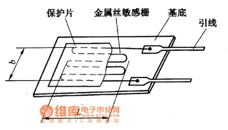
The picture shows the metal foil resistance strain gauge basic structure circuit. (View)
View full Circuit Diagram | Comments | Reading(1076)
| Pages:1578/2234 At 2015611562156315641565156615671568156915701571157215731574157515761577157815791580Under 20 |
Circuit Categories
power supply circuit
Amplifier Circuit
Basic Circuit
LED and Light Circuit
Sensor Circuit
Signal Processing
Electrical Equipment Circuit
Control Circuit
Remote Control Circuit
A/D-D/A Converter Circuit
Audio Circuit
Measuring and Test Circuit
Communication Circuit
Computer-Related Circuit
555 Circuit
Automotive Circuit
Repairing Circuit