Control Circuit
The FSK modulation circuit composed of 74LS74
Published:2011/7/14 5:57:00 Author:Borg | Keyword: FSK modulation | From:SeekIC

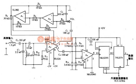
This is the FSK modulation circuit composed of 74LS74. The FSK modulation circuit has neither PLL nor bandpass filter with high Q value, so there is no need of any tune adjustment in the high-frequency modulation circuit. The 2 tune circuits composed of L1, L2, C4 and C7 is working as the input filter, which only allows the frequency band with central frequency of 10MHZ to pass, and the high frequency difference amplifier A3 can amplify the 10MHZ signal. The auto gain control (AGC) circuit is composed of A1 and A2. The HF signal, which is magnified by A3, can be switched into digital signal by comparator A4.
Reprinted Url Of This Article:
http://www.seekic.com/circuit_diagram/Control_Circuit/The_FSK_modulation_circuit_composed_of_74LS74.html
Print this Page | Comments | Reading(3)

Article Categories
power supply circuit
Amplifier Circuit
Basic Circuit
LED and Light Circuit
Sensor Circuit
Signal Processing
Electrical Equipment Circuit
Control Circuit
Remote Control Circuit
A/D-D/A Converter Circuit
Audio Circuit
Measuring and Test Circuit
Communication Circuit
Computer-Related Circuit
555 Circuit
Automotive Circuit
Repairing Circuit
Code: