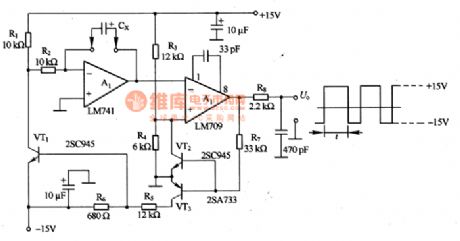
Measuring and Test Circuit
The capacitance test circuit composed of LM741
Published:2011/7/14 4:57:00 Author:Borg | Keyword: capacitance, test circuit | From:SeekIC

In figure 8-3 is the capacitance test circuit composed of LM741. The test principle of the circuit that the capacitor Cx under test is charging/discharging to generate a triangular wave, if the period of the wave is tested, the volume of the capacitor is known. The Miller integrating circuit can be composed of A1, and the Miller circuit composed of A2 is forming forward and backward feedbacks so the oscillation is generated, whose amplitude is decided by R4 and R3, equal to 1/3 of the power supply voltage. The charge current of Cx is decided by power supply circuit and R2, the discharging current is decided by the power supply voltage and (R1+R2). In principle, oscillating is not affected by the power supply voltage.
Reprinted Url Of This Article:
http://www.seekic.com/circuit_diagram/Measuring_and_Test_Circuit/The_capacitance_test_circuit_composed_of_LM741.html
Print this Page | Comments | Reading(3)

Article Categories
power supply circuit
Amplifier Circuit
Basic Circuit
LED and Light Circuit
Sensor Circuit
Signal Processing
Electrical Equipment Circuit
Control Circuit
Remote Control Circuit
A/D-D/A Converter Circuit
Audio Circuit
Measuring and Test Circuit
Communication Circuit
Computer-Related Circuit
555 Circuit
Automotive Circuit
Repairing Circuit
Code: