Control Circuit
Single Power Low Voltage Bandpass Filter Circuit
Published:2011/7/11 2:42:00 Author:Joyce | Keyword: Single Power, Low Voltage, Bandpass , Filter | From:SeekIC


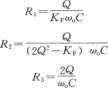
As shown in the figure is a single power low voltage bandpass filter circuit. The circuit uses a single power amplifier 8FC7 to constitute a second-order band-pass filter. Its power supply voltage ranges from 3 V to 30 V. When deciding the value of its component, one needs to identify the center frequency f0 of the band-pass filter, then chooses a suitable capacitance C (C = C1 = C2) according to the following table. After that one should determine the value of Q. which represents a parameter of characteristics of frequency selection. If the value of Q is high, bandpass will be narrow. When Q is 10, one will get a response frequency of - 40 dB every octave. But if the value of Q is too large, the circuit will not be stable. The values of R1, R2, and R3 can be calculated based on the following 3 formulas.
Reprinted Url Of This Article:
http://www.seekic.com/circuit_diagram/Control_Circuit/Single_Power_Low_Voltage_Bandpass_Filter_Circuit.html
Print this Page | Comments | Reading(3)

Article Categories
power supply circuit
Amplifier Circuit
Basic Circuit
LED and Light Circuit
Sensor Circuit
Signal Processing
Electrical Equipment Circuit
Control Circuit
Remote Control Circuit
A/D-D/A Converter Circuit
Audio Circuit
Measuring and Test Circuit
Communication Circuit
Computer-Related Circuit
555 Circuit
Automotive Circuit
Repairing Circuit
Code: