
Circuit Diagram
Index 998
LOW_CPST_COMPARATOR_AND_DISPLAY
Published:2009/7/7 3:54:00 Author:May

An op amp is used as a comparator and a sink for LED current. The output voltage of the amplifier changes about 1.4 V depending on the direction of the current. Only one transistor is on at any time. Maximum LED current is limited to 25 mA by overcurrent protection of the μA741. If LEDs are not Capable of carrying such a current or an alternative op amp is used and an additional resistor Rlim is necessary. (View)
View full Circuit Diagram | Comments | Reading(541)
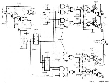
FREQUENCY_CONTROLS_SPEED
Published:2009/7/7 3:53:00 Author:May
Circuit generates variable frequency between 10 and 300 Hz at constant voltage for changing speed of induction motor between theoretical limits of 300and 9000 rpm without affecting maximum torque. Direct coupling between control and drive circuits is used; if motor noise affects control logic circuits, ptoisolators should be usedbetween control and drive sections. Article tells how circuit works and gives similar circuit using optical coupling.-T. Mazur, Unique Semiconductor Mix Controls Induction Motor Speed, EDN Magazine, Nov. 1, 1972, p 28-31. (View)
View full Circuit Diagram | Comments | Reading(1891)
TEMPERATURE_COMPENSATING_THERMOCOUPLE_BRIDGE
Published:2009/7/21 20:41:00 Author:Jessie
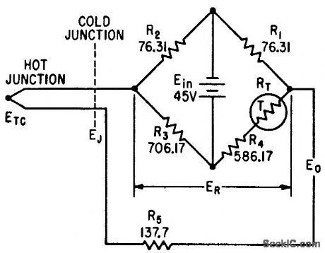
Temperature-sensitive resistor RT in bridge provides voltage to compensate variations in cold-junction voltage during missile light testing.-J. B. Brownwood, Thermocouple Compensating Circuit Design, Electronics, 35:1, p 98-100. (View)
View full Circuit Diagram | Comments | Reading(1868)
1_20_Hz_SINE
Published:2009/7/21 20:40:00 Author:Jessie

Designed to complement usual lab sine-wave generator that goes down to only 20 Hz, by providing discrete switch-selected output frequencies of 1 Hz and 2-20 Hz in 2-Hz steps. Output attenuator uses pot and switch to set output at any value within range of five decades. Circuit uses 741 opamp in Wien-bridge oscillator having four-element RC network in positive feedback path of amplifier (R6 in parallel with capacitor selected by S2A, and R7 in series with capacitor of S2B), so oscillation occurs at frequency where phase shift occurs. Article gives construction details Offset adjustment R2 may need touching up as batteries rundown.-D Hileman and L Hileman.V-V-V LF Generator,73 Magazine. Holiday issue 1976,p97-99. (View)
View full Circuit Diagram | Comments | Reading(825)
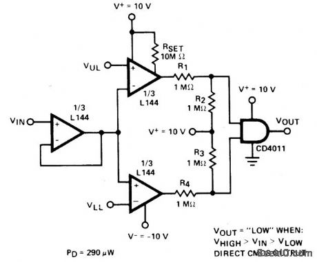
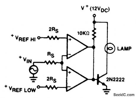
DOUBLE_ENDED_LIMIT_COMPARATOR
Published:2009/7/7 3:52:00 Author:May
View full Circuit Diagram | Comments | Reading(0)
PHOTOFEEDBACK_STABILIZATION_OF_PHOTOTRANSISTOR
Published:2009/7/21 20:40:00 Author:Jessie
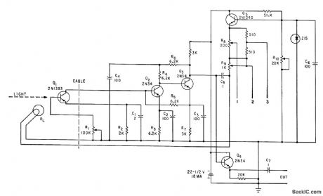
Subminiature lamp mounted on window of phototransistor stabilizes electro-optical response of high-temperatures. Base bias for phototransistor is supplied by d-c component of light from feedback lamp. -S. A. Elder, Designing Phototransistor Pyrometers With and Without Feedback, Electronics, 34:49, p 56-60. (View)
View full Circuit Diagram | Comments | Reading(755)
2_MHz_STANDARD_WITH_DIVIDERS
Published:2009/7/21 20:39:00 Author:Jessie

Can be used for calibration of frequency meters, frequency counters, and amateur receivers. Two crystal oscillators (2 MHz and 100 kHz) feed two 7490 decade counters through isolation amplifier. Arrangement gives frequency division by 2, 4, 10, 20, and 100 for each oscillator, with all frequencies rich in harmonics and usable through 144 MHz. Counter reset gates at pins 2, 3, 6, and 7 and ground at pin 10 must be connected to common terminal for all modes of operation, Supply should not exceed 5.5 V.-J. M. Janicke, A Wide-Range Crystal-Controlled Frequency Standard, QST, July 1976, p 27-28. (View)
View full Circuit Diagram | Comments | Reading(1160)
MERCURY_THERMOSTAT_AND_SCR_CONTROL_HEATER
Published:2009/7/21 20:39:00 Author:Jessie

Uses mercury-in-glass thermostat capable of sensing 0.1℃ changes. Scr serves both as current amplifier for thermostat and as main load switching element. With thermostat open, sct will trigger on each half-cycle and deliver power to heater load. When thermostat closes, scr can no longer trigger, and heater shuts off.- Silicon Controlled Rectifier Manual, Third Edition, General Electric Co., 1964, p 121. (View)
View full Circuit Diagram | Comments | Reading(1190)
LIMIT_COMPARATOR
Published:2009/7/7 3:50:00 Author:May
View full Circuit Diagram | Comments | Reading(0)
1_10_N1Hz_CRYSTAL
Published:2009/7/21 20:38:00 Author:Jessie

Stable crystal test oscillator takes any crystal in frequency range with no tuning adjustments. Uses single Motorola MC799P IC in circuit that provides 32-pF crystal loading. Trimmer may be used to adjust crystal for exact frequency if desired. Circuit is not critical. Bias pot compensates for battery voltage changes. Output attenuator uses standard resistor values to provide up to 126 dB of output signal control. Meter serves as battery tester and gives instant indication of crystal activity when circuit is used for testing crystals.-A A. Kelley, Crystal Test Oscillator and Signal Generator, Ham Radio, March 1913, p 46-47. (View)
View full Circuit Diagram | Comments | Reading(638)
TEMPERATURE_TELEMETER_FOR_BALLOON
Published:2009/7/21 20:38:00 Author:Jessie
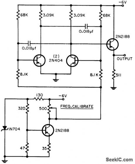
Designed for range of -70 to +70℃, for which circuit produces frequency change of 1.5 kc. Uses temperature-sensitive base-to-emitter voltage of transistor, which varies linearly with temperature, as transducer for voltage-controlled oscillator based on astable mvbr.-G. F. Ingle, Using Transistors for Temperature Measurement, EEE, 11:8, p 53-55. (View)
View full Circuit Diagram | Comments | Reading(544)
1_Hz_TO_1_MHz
Published:2009/7/21 20:35:00 Author:Jessie

Low-cost secondary frequency standard generates marker signals of 1000, 500, 100, 50, 25, 10, 5, and 1 kHz and 100, 10, and 1 Hz, with harmonic markers usable well beyond 30 MHz. Two TTL output levels are available as clocks or signal injectors for checking TTL.Short-term accuracy is about 1 part in 106. Unit is easily aligned to WWV with shortwave receiver. Frequency-burst mode turns output on and off 10 times per second, for identification of markers in crowded band of receiver. Article covers construction and operation in detail, and gives circuit for suitable regulated power supply having standby battery.-T. Shankland, Build a Super Standard, 73Magazine, Oct. 1976, p 66-69. (View)
View full Circuit Diagram | Comments | Reading(0)
VOLTAGE_MONITOR_COMPARATOR
Published:2009/7/7 3:49:00 Author:May

A portion of the monitored voltage (deter-mined by R1's adjustment) is compared to a fixed voltage obtained from a zener reference network, R2-D1. As long as the monitored volt-age remains at or above its present monitor point (determined by R1's setting), the output indicator, LED1, remains dark. If the voltage drops below this level, the LED goes on. D1 is a 3.3-V zener. A 12 Vdc power supply is suitable for monitoring input voltages of up to 12 volts. (View)
View full Circuit Diagram | Comments | Reading(836)
CLAMPED_DARLINGTON_CONTROL
Published:2009/7/7 3:48:00 Author:May
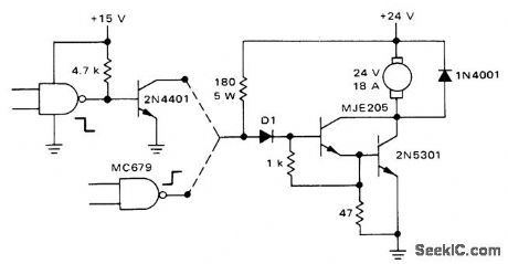
Circuit uses MJE205 5-A transistor in Darlington con-figuration driving 2N5301 30-A transistor for passing 18 A to DC motor under logic control.CMOS gate connections are shown for energizing motor when logic is low and when logic is high.-A. Pshaenich, Interface Techniques Between Industrial Logic and Power Devices, Motorola, Phoenix, AZ, 1975, AN-712A, p 19. (View)
View full Circuit Diagram | Comments | Reading(715)
SECONDARY_STANDARD
Published:2009/7/21 20:33:00 Author:Jessie

Provides switch selected square-wave outputs of 100, 20, 10, 5, and 1 kHz, calibrated with receiver tuned to WWV frequency. 100-kHz clock signal is generated by crystal oscillator IC1. Half of IC2 is buffer between oscillator and first decade counter IC3, used to generate 10- and 20-kHz outputs. Sec-ond decade counter IC4 gives 1 and 5 kHz.-E.R. Spadoni, A Versatile Secondary Frequency Standard, CQ, Sept. 1975, p 31-32. (View)
View full Circuit Diagram | Comments | Reading(688)
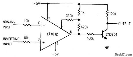
LOW_POWER_COMPARATOR_WITH_LESS_THAN_10_μV_HYSTERESIS
Published:2009/7/7 3:47:00 Author:May
View full Circuit Diagram | Comments | Reading(515)
TRIAC_SPEED_CONTROL_WITH_FEEDBACK
Published:2009/7/7 3:45:00 Author:May
Feedback is derived from load current, eliminating need for separate connections to motor field and armature windings. When triac conducts, normal line voltage less drop across triac and R5 is applied to motor. If firing of triac is delayed in each half of AC cycle, RMS voltage of motor is reduced and speed is correspondingly reduced. Feedback maintains torque at reduced speeds. Value of R5 in ohms is equal to 2 divided by rated RMS motor current in amperes and is 0.32 ohm for 6.5-A induction motor. Suitable for use with electric drills, where good torque is obtained down to about one-third of maximum speed.- Circuit Applications for the Triac, Motorola, Phoenix, AZ, 1971, AN-466, p 7. (View)
View full Circuit Diagram | Comments | Reading(2705)
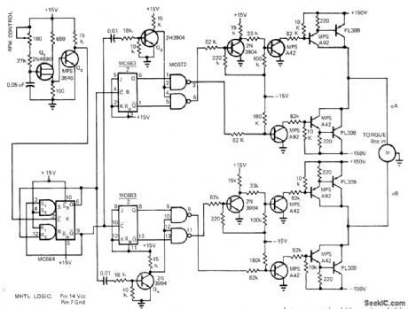
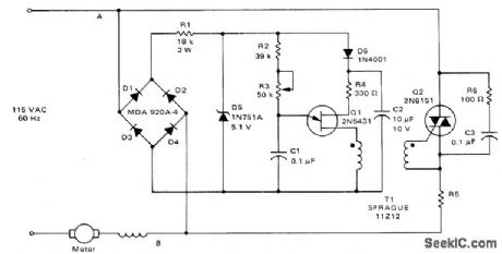
SPEED_CONTROL_FOR_INDUCTION_MOTOR
Published:2009/7/7 3:40:00 Author:May
Uses UJT oscillator Q1 to generate frequency in range from 40 to 1200 Hz for feeding to divide-by-4 configuration that gives motor source frequency range of 10 to 300 Hz. With induction motor having two pairs of poles, this gives theoretical speed range of 300 to 9000 rpm with essentially constant torque. Speed varies linearly with frequency. Circuit uses pair of flip-flops (MC673) operated in time-quadrature to perform same function as phase-shifting capacitor so motor receives two drive signals 90° apart. Article covers operation of circuit in detail. Optoisolators are used to provide bipolar drive signals from unipolar control signals. Each output drive circuit is normally off and is turned on only when its LED is on. If logic power fails, drives are disabled and motor is turned off as fail-safe feature.-T. Mazur, Unique Semiconductor Mix Controls Induction Motor Speed, EDN Magazine, Nov. 1, 1972, p28-31. (View)
View full Circuit Diagram | Comments | Reading(865)
BODY_TEMPERATURE_TRANSISTOR_THERMOMETER
Published:2009/7/21 21:17:00 Author:Jessie
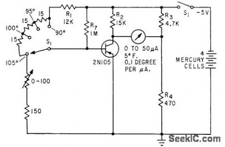
Covers range of 90°to 105°F in three steps, with , temperature indicated on meter that measures base bias of germanium transistor, for which bias varies linearly with temperature.-L. E. Barton, Measuring Temperature with Diodes and Transistors, Electronics, 35:18, p 38-40. (View)
View full Circuit Diagram | Comments | Reading(785)
WIDE_RANGE_DIODE_THERMOMETER
Published:2009/7/21 21:14:00 Author:Jessie

Temperature-sensing germanium-diode bucking-vott-age microammeter has null indicator, covers full usable range of from near absolute zero to about 45℃ with resistance values shown. -L. E. Barton, Measuring Temperature with Diodes and Transistors, Electronics, 35:18, p 38-40. (View)
View full Circuit Diagram | Comments | Reading(646)
| Pages:998/2234 At 209819829839849859869879889899909919929939949959969979989991000Under 20 |
Circuit Categories
power supply circuit
Amplifier Circuit
Basic Circuit
LED and Light Circuit
Sensor Circuit
Signal Processing
Electrical Equipment Circuit
Control Circuit
Remote Control Circuit
A/D-D/A Converter Circuit
Audio Circuit
Measuring and Test Circuit
Communication Circuit
Computer-Related Circuit
555 Circuit
Automotive Circuit
Repairing Circuit