
Circuit Diagram
Index 996
SERIES_WOUND_MOTOR
Published:2009/7/7 4:06:00 Author:May
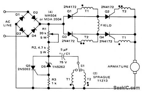
Provides both direction and speed control for fractional-horsepower series-wound or universal DC motors as long as motor current requirements are within SCR ratings. Q1-Q4, connected in bridge, are triggered in diagonal pairs. S1 determines which pair is turned on, to provide direction control. Pulse circuit is used to drive SCRs through T1 or T2. When C1 charges to break-down voltage of zener Q5, zener passes current to gate of SCR Q5 and turns it on. This discharges C1 through T1 or T2 to create desired triggering pulse. Q5 stays on for duration of half-cycle. R1 controls motor speed by changing time required to charge C1, thereby changing conduction angle of Q1-Q4 or Q2-Q3.- Direction and Speed Control for Series, Universal and Shunt Motors, Motorola, Phoenix, AZ, 1976, AN-443. (View)
View full Circuit Diagram | Comments | Reading(2379)
DEMONSTRATION_COMPARATOR_CIRCUIT
Published:2009/7/7 4:05:00 Author:May
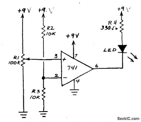
This circuit is an op amp without a feedback resistor. R2 and R3 junction point sets the reference voltage. When the input voltage set by R1 is below the reference voltage the LED glows. If voltage is above reference, the LED goes off. (View)
View full Circuit Diagram | Comments | Reading(1687)
FREQUENCY_COMPARATOR
Published:2009/7/7 4:04:00 Author:May
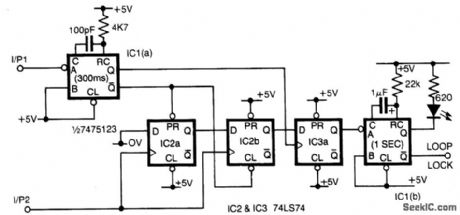
Input 1 is used as a gating period, during which a single rising edge on input 2 will cause a logic 1 output-any other number, indicating non-identical frequencies causes a logic 0 output. IC1a converts input 1 to a narrow pulse which initializes IC2 which forms a two-stage shift register clocked by input 2. On the first edge of input 2 a logic 1 appears on the output of IC2b and for all subsequent inputs a logic 0 is present. At the end of the gating period this output is latched by IC3 forming the lock output. As this is only valid for one input period a monostable is added to the output to enable, for example, visual monitoring of the output. Either output from IC3 can be used depending on which state is most important. As connected the failure state is indicated. (View)
View full Circuit Diagram | Comments | Reading(0)
HARNESS_TESTER_USES_NEON_FLIP_FLOPS
Published:2009/7/21 22:01:00 Author:Jessie
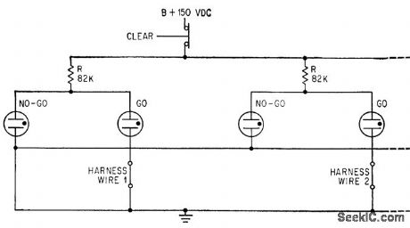
One end of each harness wire under lest is grounded. Other end completes circuit for GO glow lamp. Discontinuity in wire opens GO cathode, decreases voltage drop through R, and makes NO-GO lamp glow.-Harness Tester Detects and Indicates Intermittent Faults, Electronics, 37:4, p 56-57. (View)
View full Circuit Diagram | Comments | Reading(460)
3_30_MHz_QUADRATURE_PHASE_SHIFT
Published:2009/7/21 22:00:00 Author:Jessie
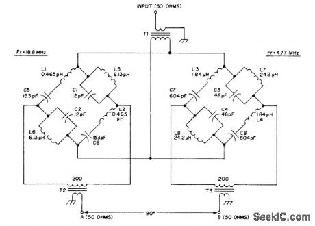
Wide-band passive AF phaseshift network makes direct-conversion SSB generation possible Bridge networks each provide 45°phase shift, to give differential phase shift of 90°over entire frequency range with maximum phase error of about 1° Overall loss of network is about 6 dB,T1,T2,and T3 are wound on Neosid 1050-1-F14 of Indiana General F684-1 balun core. Twist together three 7-inch lengths of No. 26 enamel and wind 3 turns through the two holes. Connect two wires in series for 200-ohm windings. Article gives data for winding all other coils.-R. Harrison, A Review of SSB Phasing Teqhniques, Ham Radio, Jan. 1978, p 52-62. (View)
View full Circuit Diagram | Comments | Reading(1694)
NUCLEAR_RESONANCE_SENSOR
Published:2009/7/21 21:36:00 Author:Jessie
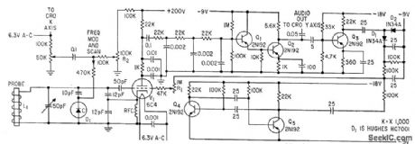
Temperature telemeter depends on absorption of r-f energy by chlorine molecule in proportion to temperature. When spectrometer oscillator V1 is tuned to frequency of correct absorption line, each oscillator pulse sets up oscillations in probe that last long enough to affect starting voltage for next oscillator pulse. After plate detection and low-pass filtering to suppress quench frequency, signal goes to two-stage a-f amplifier Q1-Q2, whose output to cro indicates whether spectrometer is on nuclear resonance frequency.-C. Dean, Using Nuclear Resonance to Sense Temperature, 33:28, Electronics, p 52-54. (View)
View full Circuit Diagram | Comments | Reading(509)
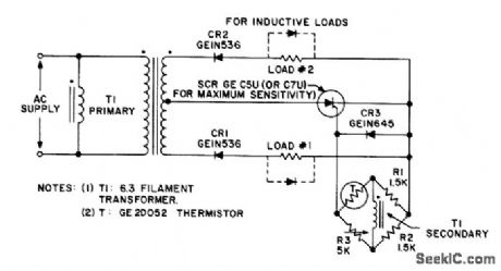
Enlarger_phototimer
Published:2009/7/21 21:36:00 Author:Jessie

Enlarger phototimer (courtesy General Electric Company). (View)
View full Circuit Diagram | Comments | Reading(638)
SOFT_CLIPPER
Published:2009/7/21 21:34:00 Author:Jessie

Used after audio compressor to improve effective signal strength of SSB transmitter. Soft clipping is achieved by driving diode pair through resistance. Clipper is followed by low-noise FET voltage amplifier having broadband flat frequency response. Output filter sharply attenuates signals above about 3 kHz.-J,J,Schultz, Adding das to the Audio Compressor,73 Magazine, May 1974,p21-23and 25. (View)
View full Circuit Diagram | Comments | Reading(1875)
TEMPERATURE_DRIFT_CONTROL
Published:2009/7/21 21:34:00 Author:Jessie
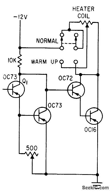
Used to minimize thermal drift in d-c amplifer. Temperature-sensing element Q1 controls current through heater of temperature-controlled block. Base of Q1 is left floating. Variations in ambient temperature are reduced by factor of 10 inside block, and transistors are maintained at 40℃.-A. Patton, Telemetry System for Testing Automobiles, Electronics, 33:43, p 57-59. (View)
View full Circuit Diagram | Comments | Reading(630)
CONTROL_CIRCUIT_FOR_PHOTOFEEDBACK_PYROMETER
Published:2009/7/21 21:33:00 Author:Jessie
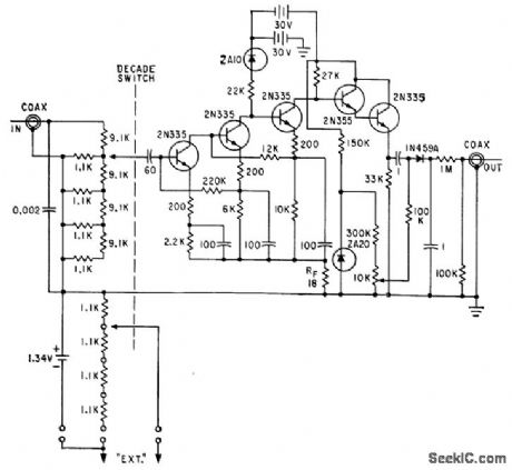
Decade amplifer of conventional phototransistor pyrometer control was modifed by removing output transformer and load inductor, lo give additional feed-back at low frequencies. Bootstrap emitter. follower stage was added as output buffer to improve circuit stability. Used for measuring high rocket surface temperatures.-S. A. Edler, Designing Phototransistor Pyrometers With and Without Feedback, Electronics, 34:49, p 56-60. (View)
View full Circuit Diagram | Comments | Reading(793)
SIDEBAND_MIXER
Published:2009/7/21 21:32:00 Author:Jessie
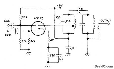
Used as transmitting mixer in SSB transceiver made by Sideband Associates for radiomarine communication in 2-23 MHz range. Low-frequency sideband signal and high-frequency oscillator signal are mixed to produce higher sum frequency at output.Double-tuned resonant circuit provides adequate output bandwidth and excellent skirt rejection of undesired frequency components.-E. Noll, MOSFET Circuits, Ham Radio, Feb. 1975, p 50-57. (View)
View full Circuit Diagram | Comments | Reading(732)
Basic_SCR_phase_control
Published:2009/7/21 21:31:00 Author:Jessie

This circuit shows a basic phase-control scheme using an SCR and relaxation oscillator. The capacitor is charged through the resistor until the breakover voltage of the trigger (an SBS in this case) is reached. The SBS then changes to the on-state, and the capacitor is discharged through the SCR gate. Turn-on of the SCR is accomplished with a short, high-current pulse. In addition to an SBS, commonly-used triggers are UJTs, PUTs, optically coupled thyristors (chapter 9), and SIDACs. Phase control is obtained by varying the RC time constant of the charging circuit so that the trigger turn-on occurs at varying phase angles within a controlled half cycle. With the values shown, the conduction angle can be varied from about 20°to 150°. (View)
View full Circuit Diagram | Comments | Reading(1098)
OVER_UNDER_TEMPERATURE_MONITOR
Published:2009/7/21 21:30:00 Author:Jessie
Dual output can be used to drive high and low temperature indicator lamps or relays. Balanced bridge may also be used to trigger conventional scrload combinations.- Silicon Controlled Rectifier Manual, Third Edition, General Electric Co., 1964, p 120. (View)
View full Circuit Diagram | Comments | Reading(626)
OFF_AIR_MONITOR
Published:2009/7/21 21:29:00 Author:Jessie
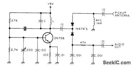
Single-frequency modulation monitor for SSB transmitter combines crystal oscillator with product detector, for checking audio at one point within band. If tuning and loading of SSB transmitter are same over rest of band, audio quality also remains constant. Use fundamental-mode crystal for desired band. LC circuit should be resonated to band being used. Oscillator signal is spotted with transceiver in receive mode, after which transceiver can be monitored during transmissions.-Clean Up Your Act, 73 Magazine, Jan.1978, p 136-137. (View)
View full Circuit Diagram | Comments | Reading(1095)
SPEECH_PROCESSOR
Published:2009/7/21 21:27:00 Author:Jessie

Preamplification combined with dipping or compression gives higher average level and increased intelligibility of SSB communication. Degree of compression is controlled with 100K pot that adjusts input. Output of transistor feeds passive diode compressor.Amount of compression will vary with diode type, and experimentation is suggested. Article covers construction and adjustment of circuit.-B. Barrington, Simple Audio Preamp.73Magazl'ne, Feb. 1974, p 69-70. (View)
View full Circuit Diagram | Comments | Reading(5010)
PULSED_BRAKE
Published:2009/7/7 4:02:00 Author:May
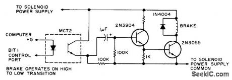
Transition from high (1) to Dow (0) at control port of microprocessor energizes brake solenoid of paper-tape, reader in pulses lasting several microseconds, with time determined by size of capacitor used. Energizing of solenoid squeezes tape between top of solenoid and flat iron brake shoe that is attracted by solenoid. Unmarked resistor is 1K.-D. Hogg, The Paper Taper Caper, Kilobaud, March 1977, p 34-40. (View)
View full Circuit Diagram | Comments | Reading(2279)
HIGH_INPUT_IMPEDANCE_WINDOW_COMPARATOR
Published:2009/7/7 4:02:00 Author:May
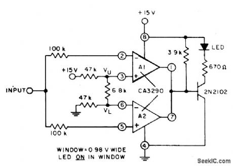
The circuit uses both halves of the CA3290 BiMOS dual voltage comparator. The LED will be turned 0N whenever the input signal is above the lower limit (VL) but below the upper limit (VU). (View)
View full Circuit Diagram | Comments | Reading(569)
HYBRID_THERMOSTAT
Published:2009/7/21 20:33:00 Author:Jessie
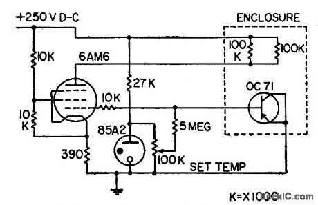
Utilizes reverse characteristics of pnp junctions for temperature control. Provides continuous control with higher sensitivity than thermistors, along with quiet operation, remote resetting of temperature, and small thermal time constant. Chief disadvantage is high impedance.-H. Sutcliffe, Transistor Temperature Controller, Electronics, 31:13, p 81-84. (View)
View full Circuit Diagram | Comments | Reading(670)
THERMISTOR_IS_SENSOR_FOR_OVEN_CONTROL
Published:2009/7/21 20:31:00 Author:Jessie
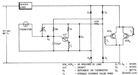
When oven temperature drops, thermistor resistance increases, making unijunction transistor trigger earlier in line voltage cycle so scr's deliver more power to oven. -J. C. Hey, The Widening World of the SCR, Electronics, 37:25, p 78-85. (View)
View full Circuit Diagram | Comments | Reading(787)
AF_RF_FROM_1_MHz
Published:2009/7/21 20:31:00 Author:Jessie

String of SN7490 decade counters divides output of 1-MHz crystal oscillator by 10 or 2 to give choice of six fixed frequencies between 1000 Hz and 100 kHz along with undivided 1 MHz. 0ne gate of SN7400 crystal oscillator drives LED to indicate that crystal is oscillating, When using external sine-wave source, input is squared by SN74121 MVBR for driving frequency divider chain. Circuit is easily modified to give other divider ratios. Applications include use as marker generator for receiver calibration up into VHF range or as signal generator for precise AF or PF square-wave signal at desired frequencies,-J,J Schultz, Poor Man's Universal Frequency Generator,73 Magazine, July 1974.p33 and 35-36. (View)
View full Circuit Diagram | Comments | Reading(1919)
| Pages:996/2234 At 209819829839849859869879889899909919929939949959969979989991000Under 20 |
Circuit Categories
power supply circuit
Amplifier Circuit
Basic Circuit
LED and Light Circuit
Sensor Circuit
Signal Processing
Electrical Equipment Circuit
Control Circuit
Remote Control Circuit
A/D-D/A Converter Circuit
Audio Circuit
Measuring and Test Circuit
Communication Circuit
Computer-Related Circuit
555 Circuit
Automotive Circuit
Repairing Circuit