
Circuit Diagram
Index 984
LONG_RANGE_OBJECT_DETECTOR
Published:2009/7/7 8:20:00 Author:May

When long ranges must be worked with IR light sources, and when high system reliability is required, pulsed-mode operation of the IR is required. Additional reliability of operation is attained by synchronously detecting the photodetector current, as this circuit does. PC-1 is an IR and phototransistor pair which detect the presence of an object blocking the transmission of light from the IR to the phototransistor. Rela-tively long-distance transmission is obtained by pulsing the IR, with about 10-pts pulses, at a 2-ms period, to 350 mA via the 2N6027 oscillator. The phototransistor current is amplified by the 2N5249 and 2N5356 amplifier to further increase distance and allows use of the H11A5, also pulsed by the 2N6027, as a syn-chronous detector, providing a fail-safe, noise immune signal to the 2N5249 pair forming a Schmitt-trigger output.This design was built for battery operation, with long battery life a primary consideration. Note that another stage of amplification driving the IR can boost the range limited by the IR VF, by 5 to 10 times. A higher supply voltage for the IR can double this range.Today, optoelectronics are mostly used to transmit electronic information over light beams. These applications range from the use of optocouplers transmitting information between IC logic circuits and power circuits, between power lines and signal circuits, between telephone lines and control circuitry, to the pulse-modulated systems which transmit information through air or fiber optics over relatively great distances. (View)
View full Circuit Diagram | Comments | Reading(1040)
INFRARED_WIRELESS_SPEAKER_SYSTEM
Published:2009/7/7 8:17:00 Author:May

Although the IR region is free from radio interference, it is subject to interference front incandescent lamps, fluorescent lamps, stray reflections, and other sources.A simple way to overcome that problem is to create a carrier by chopping the IR radiation at a rate of 100 kHz. The audio then modulates the carrier by modulating the chopping rate. A receiver then detects the IR beam as a 100-kHz FM signal. The only disadvantage is that instead of a simple audio amplifier, a high-gain FM receiver is necessary. However, with the ICs that are now available, an FM receiver is easy to build, and contains little more circuitry than a high-gain audio amplifier. The kit is available from North Country Radio, P.O. Box 53, Wykagyl Station, NY 10804. (View)
View full Circuit Diagram | Comments | Reading(1661)
TONE_DECODER
Published:2009/7/7 8:10:00 Author:May

Adding a pair of one shots to the output of a 567 tone decoder renders it less sensitive to out-of-band signals and noise. Without the one shots, the 567 is prone to spurious output chatter. Other protection schemes, such as feeding back outputs or using an input filter, do not work as well as the one shots. The output of the 567 is high in the absence of a tone and becomes low when it detects a tone. The tone decoder triggers a one shot via an AND gate. The one shot's period is set to slightly less than the duration of a tone burst.
When the output of the tone decoder decreases, it triggers the second one shot. The second one shot's period is set to slightly less than the interval between tone bursts. The flip-flop enables and disables the inputs to one shots so that spurious outputs from the tone decoder do not affect the output.
(View)
View full Circuit Diagram | Comments | Reading(0)
ON_THE_AIR_INDICATOR
Published:2009/7/7 8:08:00 Author:May

The circuit is a simple rf-actuated switch which will respond to any strong fteld in the region of the pickup wire. The length of the wire will depend on how much coupling is needed, but a 250-mm length wrapped around the outside of the coaxial cable feeding the antenna should sufflce for most power levels. If only one band is used, the wire can be made a resonant length-495 mm for 144 MHz band operation for example. When rf energy is picked up by the device, diode D1 will conduct on the negative half-cycles, but will be cut off on the positive half-cycles. The result will be a net positive voltage at the base of transistor Tr1, forward biasing it into conduction. On ssb and cw transmissions, where the transmission is not continuous, that bias would be constantly varying and the relay RLA would chatter. However, capacitor C2 holds the bias voltage steady until a long gap in transmissions occurs. (View)
View full Circuit Diagram | Comments | Reading(1049)
RF_ACTUATED_RELAY
Published:2009/7/7 8:08:00 Author:May
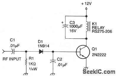
Automatic antenna switching or rf power indi-cation can be achieved with this circuit. Relay will key with less than 150 mW drive on 2 m. (View)
View full Circuit Diagram | Comments | Reading(1695)
Serial_data_transfer_circuit_into_shift_registers_with_parallel_output_to_data_bus
Published:2009/7/21 8:22:00 Author:Jessie

Serial data transfer circuit into shift registers with parallel output to data bus (courtesy Analog Devices, Inc.). (View)
View full Circuit Diagram | Comments | Reading(1453)
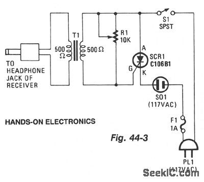
RECEIVER_SIGNAL_ALARM
Published:2009/7/7 8:06:00 Author:May
View full Circuit Diagram | Comments | Reading(698)
SCR_IMPROVES_SCHMITT_TRIGGER_STABILITY
Published:2009/7/21 8:08:00 Author:Jessie
Input signals to 200 kc give consistent triggering over wide range of temperature, source impedance, and input impedance, and hysteresis is reduced by order of 10.-M.Schmidt, Improved Schmitt Trigger Uses SCR, Electronics, 36:17, p 68. (View)
View full Circuit Diagram | Comments | Reading(775)
VISUAL_LEVEL_INDICATOR
Published:2009/7/7 8:05:00 Author:May


This indicator is basically a switch with hysteresis characteristics. If the input voltage momentarily (or permanently) exceeds the most positive refer-ence level, LED1 is switched on. If, on the other hand, the voltage falls below the negative, or least positive, reference level, LED1 will be switched off and LED2 switched on. The output voltage, VO is clamped either to the diode voltage VD1 , orVD2 depending on which LED is conducting. ForVO to be positive, VB has to be positive with respect to the reference voltage VR; for VO to be negative, VB has to be negative with respect to VR. (View)
View full Circuit Diagram | Comments | Reading(759)
M6800_microprocessor_to_115_volt_AC_load_interface_using_optically_coupled_MOC3011_triac_drivers
Published:2009/7/21 8:08:00 Author:Jessie
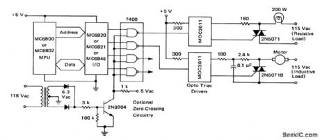
M6800 microprocessor to 115-volt AC load interface using optically coupled MOC3011 triac drivers (courtesy Motorola Semiconductor Products Inc.). (View)
View full Circuit Diagram | Comments | Reading(1705)
SECOND_AUDIO_PROGRAM_ADAPTER
Published:2009/7/7 8:02:00 Author:May
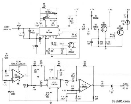
The baseband-audio input comes from the pole of switch S1 in the stereo decoder, and is coupled to IC1 (a CA3089) via a 78.6 kHz bandpass filter that consists of capacitors C1 and C2, and inductor L1. IC1 is a combination i-f amplifier and quadrature detector normally used for FM radio systems operating within an i-f of 10.7 MHz. The device works equally well at 78.6 kHz. Capacitors C6 and C7, and inductor L2 tune the detector section to 78.6 kHz, while C5 provides the necessary 90-degree phase shift for proper quadrature detector operation. The output voltage at pin 13 of IC1 is proportional to the level of the incom-ing signal. When the voltage at the wiper of potentiometer R3 reaches a predetermined threshold level, Q1 conducts, grounding pin 5 of IC1, enabling 101's mute function.
Detected audio output from pin 6 of IC1 goes to IC2a, which is configured as a 12-kHz, -12 dB per octave, low-pass filter. The output of IC2a appears across potentiometer R10, which provides a means of adjusting the drive level into IC3b, the 2:1 compander.
Audio from the wiper of R10 is split into two paths: a high-pass filter (C14 and R8) provides a path to the rectifier input of the compander, and a bandpass filter (R9, C16, and C15) that feeds the audio input of the compander. A fixed 390-μs de-emphasis network is formed by C18 and R11 in conjunction with IC3b, Corrected audio appears at pin 10 of IC3b and is coupled to IC2b, and output buffer amplifier.
Audio from pin 6 of IC1 is also coupled to an audio high-pass filter, R5 and C10, and fed to an audio rectifier, D1, D2, and C11. When a SAP signal is detected by IC1, it is rectified by D1 and D2; the resultant dc charges C11. An increasing positive voltage at the base of Q2 causes its current flow to decrease, so the voltage at Q2's collector also decreases. That in turn causes the base voltage of Q3 to drop, which causes Q3 to conduct, thereby lighting the LED. (View)
View full Circuit Diagram | Comments | Reading(2798)
CUTOFF_SCHMITT
Published:2009/7/21 8:07:00 Author:Jessie
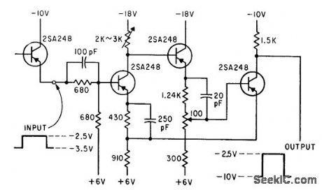
Conventional current-feedback version, In which one of the two active transistor elements is generally cut off, Per-forms reliably even though optimum operating regions for transistors cannot always be achieved.-H. Inose, Y. Yoshida, and H. Toda, Noncutoff Circuits Improve Trigger Switching, Electronics, 35:30, p 36-39. (View)
View full Circuit Diagram | Comments | Reading(698)
Color_TV_subcarrier_generator
Published:2009/7/21 8:06:00 Author:Jessie
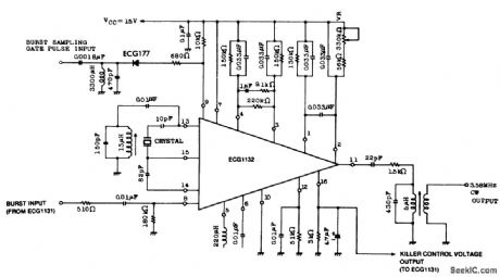
Color TV subcarrier generator. The crystal shown is for 3.58 MHz. The ECG1131 noted on the schematic is a chroma signal amplifier. The ECG1132 is a 16-pin DIP (courtesy GTE Sylvania Incorporated). (View)
View full Circuit Diagram | Comments | Reading(662)
STEREO_INDICATOR
Published:2009/7/7 8:00:00 Author:May

On most FM tuners, the stereo indicator lights upon detection of the 19-kHz pilot tone. However, this doesn't mean that the program is actually stereophonic, since the pilot tone is often transmitted with mono programs also. A similar situation exists on stereo amplifiers, where the stereo LED is simply con-trolled from the mono/stereo switch.The LED-based stereo indicator described here lights only when a true stereo signal is fed to the inputs. Differential amplifier A1 raises the difference between the L and R input signals. When these are equal, the output of A1 remains at the same potential as the output of A2, which forms a virtual ground rail at half the supply voltage. When A1 detects a difference between the L and R input signals, it supplies a positive or negative voltage with respect to the virtual ground rail, and so causes C3 to be charged via D1 or C4 via D2. Comparator A3/A4 switches on the LED driver via OR circuit D3/D4. The input signal level should not be less than 100 mV to compensate for the drop across Dl or D2. The sensitivity of the stereo indicator is adjustable with P1. (View)
View full Circuit Diagram | Comments | Reading(1494)
SCR_TRIGGER
Published:2009/7/21 8:06:00 Author:Jessie
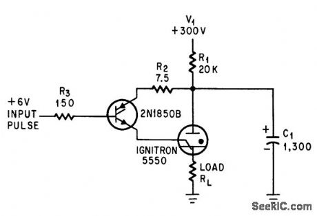
Silicon controlled rectifier triggers ignitron when 6-v pulse is applied to gate.-L. E. Frenzel, Jr., Silicon Controlled Rectifier Triggers ignition, Electronics, 37:17, p 62-63. (View)
View full Circuit Diagram | Comments | Reading(1346)
LOW_COST_HUMIDITY_SENSOR
Published:2009/7/7 7:59:00 Author:May
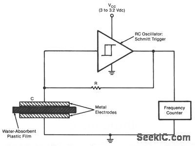
The sensor is an RC oscillator in which a water-absorbent plastic film is the insulator in the capacitive element. The capacitance of the film increases with the amount of water it absorbs from the air, and thus reduces the oscillation frequency. A frequency counter produces a digital output that represents the change in frequency and hence the change in relative humidity. The sensor can be used to measure humidity in the atmosphere, in the soil, and in industrial gases, for example. A Schmitt-trigger-type IC is con-nected to the capacitor, which consists of a film of a commercially produced sulfonated fluorocarbon polymer, 2 in. (5.08 cm) square, sandwiched between perforated metal plates. The oscillation frequency decreases almost linearly from about 100 to 16 kHz as the relative humidity increases from about 20 to 76%. (View)
View full Circuit Diagram | Comments | Reading(1156)
MICROWATTS_AT_QUIESCENCE
Published:2009/7/21 8:05:00 Author:Jessie

Circuit has same characteristics as single unijunction transistor but dissipates only microwatts of power when off.-R. A. Wilson, Pnp Plus Npn Equals Unijunction transistor, Electronics, 38:5, p 94-95. (View)
View full Circuit Diagram | Comments | Reading(1520)
Cotor_TV_chroma_signal_amplifier
Published:2009/7/21 8:05:00 Author:Jessie

Cotor TV chroma signal amplifier. The EGG 1131 isa 16-pin DIP and conststs of a chromaamplifier, an ACC amplifier, aburst gate amplifier, an ACC peak detector, a color killer, aDC chroma gain control, a DC uni-color control and a balanced sampling circuit forthe burst signal. By connecting the control terminal of the unicolor and contrast terminal of the ECG1131 it is possible to control chroma gain and contrast simultaneously (courtesy GTE Sylvania Incorporated). (View)
View full Circuit Diagram | Comments | Reading(1954)
NOISE_IMMUNE_SCR_TRIGGER_GENERAIOR
Published:2009/7/21 8:05:00 Author:Jessie

Modification of line-type radar modulator gives general-purpose triggering circuit that is immune from noise. Expensive pulse-forming network of conventional scr trigger is replaced by capacitor. Sharply peaked out.put pulses are ideal for triggering radar modulators for firing strobe flash tubes. Scr conducts for 10 microsec after triggering, and C1 is negative for next 15 microsec because of ringing with L1, so false triggering can occur from low-level noise pulses for only last 5 microsec, by which time capacitor has charged enough to forward-bitts scr so large triggering pulse is again required to turn it on. Circuit is ready for next trigger 60 microsec after C1 is discharged. Maximum prr is 12 kc.-J. E. Curry, No Pulse-Forming Not.work in SCR Trigger Generator, Electronics, 39:18, p 97-98. (View)
View full Circuit Diagram | Comments | Reading(2089)
50_MHZ_VHF_CRYSTAL_OSCILLATOR
Published:2009/7/7 7:57:00 Author:May

Figure 21-14 shows a 50-MHz oscillator operating on a third harmonic. The collector's load resistor R1 has been increased because the quartz crystal's internal series resistance RS increases with frequency in the VHF range. The crystal's internal series resistance RS is 3Ω , and the transistor's minimum current gain HFE is 100. Using the same technique as for the 20 MHz oscillator, the external series RLCL equivalent load seen by the 50 MHz crystal is 5.6Ω (RL) and 1000 pF (CL). (View)
View full Circuit Diagram | Comments | Reading(1044)
| Pages:984/2234 At 209819829839849859869879889899909919929939949959969979989991000Under 20 |
Circuit Categories
power supply circuit
Amplifier Circuit
Basic Circuit
LED and Light Circuit
Sensor Circuit
Signal Processing
Electrical Equipment Circuit
Control Circuit
Remote Control Circuit
A/D-D/A Converter Circuit
Audio Circuit
Measuring and Test Circuit
Communication Circuit
Computer-Related Circuit
555 Circuit
Automotive Circuit
Repairing Circuit