
Circuit Diagram
Index 982
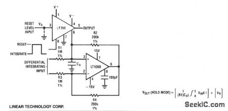
INTEGRATOR_WITH_PROGRAMMABLE_RESET_LEVEL
Published:2009/7/7 9:16:00 Author:May
View full Circuit Diagram | Comments | Reading(584)
RESETTABLE_INTEGRATOR
Published:2009/7/7 9:14:00 Author:May

The low rDS(on) and high peak current capability of the DG419 makes it ideal for discharging an integrator capacitor. A high logic input pulse disconnects the integrator from the analog input and discharges the capacitor. When the logic input lowers, the integrator is triggered. D1 and D2 prevent the capacitor from charging to over 15 V. (View)
View full Circuit Diagram | Comments | Reading(1486)
OPERATIONAL_TRIGGER
Published:2009/7/21 7:54:00 Author:Jessie
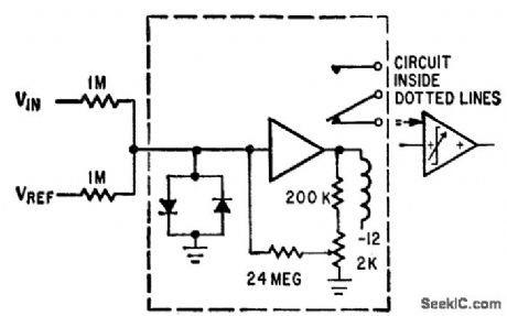
Combines some features of operational amplifier with those of Schmitt trigger. Input diodes prevent amplifier saturation.-P. Lefferts, Operational Trigger For Precise Control, Electronics, 37:28, p 50-55. (View)
View full Circuit Diagram | Comments | Reading(650)
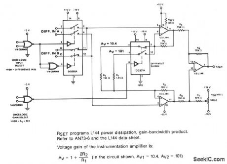
LOW_POWER_INSTRUMENTATION_AMPLIFIER
Published:2009/7/7 9:12:00 Author:May
View full Circuit Diagram | Comments | Reading(0)
THERMOCOUPLE_PREAMPLIFIER
Published:2009/7/7 9:11:00 Author:May
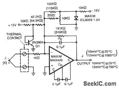
The MAX420 is operated at a gain of 191 to convert the 52 μV/'℃ output of the type J thermo-couple to a 10 mV/℃ signal. The -2.2 mV/℃ tempco of the 2N3904 is added into the summing junction with a gain of 42.2 to provide cold-junction compensation. The ICL8069 is used to remove the offset caused by the 600-mV initial voltage of the 2N3904. Adjust the 10-KΩ trimpot for the proper reading with the 2N3904 and isothermal connection block at a temperature near the center of the cir-cuit's operating range. Use the component values shown in parentheses when using a type K thermo-couple. (View)
View full Circuit Diagram | Comments | Reading(912)
ColorTV_demodulator_with_color_amplifiers
Published:2009/7/21 7:54:00 Author:Jessie

Color TV demodulator with color amplifiers. The ECG1131s shown are chroma signal amplifiers. The ECG1130 is a 16-pin DIP (courtesy GTE Sylvania Incorporated). (View)
View full Circuit Diagram | Comments | Reading(787)
DIFFERENTIAL_INSTRUMENTATION_AMPLIFIER
Published:2009/7/7 9:09:00 Author:May
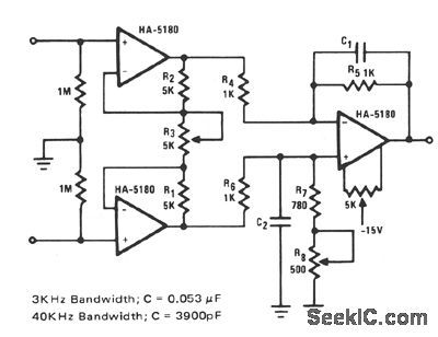
This circuit relies on extremely high input impedance for effective operation. The HA-5180 with its JFET input stage, performs well as a pre-amplifier. The standard three amplifier conftgura-tion is used with very close matching of the resistor ratios R5/R4 and (R1 + R8)/R6, to insure high common-mode rejection (CMR). The gain is con-trolled through fi3 and is equal to 2R1/R3. Additional gain can be had by increasing the ratios R5/R4 and (R7 + R8)/R6. The capacitors C1 and C2 improve the ac response by limiting the effects of transients and noise. Two suggested values are given for maximum transient suppression at fre-quencies of interest. Some of the faster DVM's are operating at peak sampling frequency of 3-kHz, hence the 4-kHz, low-pass time constant. The 40-kHz, low-pass time constant for ac voltage ranges is an arbitrary choice, but should be chosen to match the bandwidth of the other components in the sys-tem. C1 and C2 might however, reduce CMR for ac signals if not closely matched. Input impedances have also been added to provide adequate dc bias currents for the HA-5180 when open-circuited. (View)
View full Circuit Diagram | Comments | Reading(800)
NARROWBAND_162_180_MC_TRANSMIITER
Published:2009/7/21 7:53:00 Author:Jessie

First stage acts as buffer for oscillator, while Q2 and Q3 multiply frequency. Class-C power amplifier using two SM2498 transistors in parallel delivers 300 mw to 50-ohm load.-Texas Instruments Inc., Solid-State Communications, McGraw-Hill, N.Y.,1966, p 325. (View)
View full Circuit Diagram | Comments | Reading(596)
Full_wave_variable_AC_control_for_motors_and_lamps_using_a_triac_and_triac
Published:2009/7/21 7:52:00 Author:Jessie
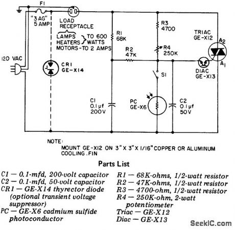
Full-wave variable AC control for motors and lamps using a triac and triac. This circuit gives full symmetrical control from 0 to 100% over the AC load. For fan or blower operation it may be desirable to place a 100-ohm 1 -watt resistor in series with a 0.1μF capacitor directly across the triac to improve performance. Best operation is achieved when the circuit is adjusted during the brightest part of the day. R4 is adjusted so that the lamp plugged into the outlet is lust off. In this manner as it gets darker the light will come on (courtesy General Electric Company). (View)
View full Circuit Diagram | Comments | Reading(1481)
BIOMEDICAL_INSTRUMENTATION_DIFFERENTIAL_AMPLIFIER
Published:2009/7/7 8:58:00 Author:May
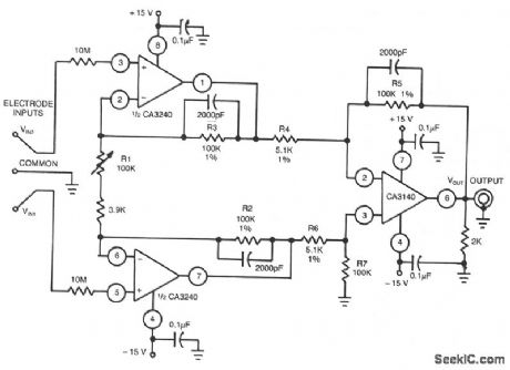
This differential amplifier uses the isolated high-impedance inputs of the CA3420 BiMOS op amp. Because the CA3240's input current is only 50 pA maximum, 10-MΩ resistors can be used in series with the input probes to limit the current to 2 μA under a fault condition. (View)
View full Circuit Diagram | Comments | Reading(1997)
735_MC_SELF_MODULATED_CRYSTAL
Published:2009/7/21 7:52:00 Author:Jessie
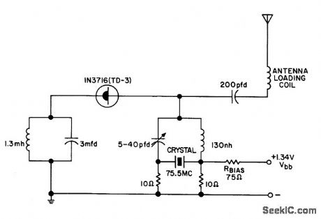
Uses tunnel diode oscillator to modulate crystal. Transistor Manual, Seventh Edition, General Electric Co., 1964, p 357. (View)
View full Circuit Diagram | Comments | Reading(903)
WIDEBAND_INSTRUMENTATION_AMPLIFIER
Published:2009/7/7 8:56:00 Author:May
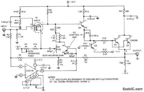
Has an input resistance of 1-MΩ, a bandwidth from dc to about 35 MHz, and a gain of 10 times. Low-frequency gain is provided by a CA3130 BiMOS op amp operated as a single-supply amplifier. High-fre-quency gain is provided by a 40673 dual-gate MOSFET. The entire amplifier is nulled by shorting the input to ground and adjusting R9 for zero dc output voltage. (View)
View full Circuit Diagram | Comments | Reading(733)
INSTRUMENTATION_AMPLFIER
Published:2009/7/7 8:55:00 Author:May
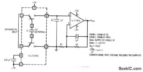
LTC1043 and LT1013 dual op amps are used to create a dual instrumentation amplifier using just two packages. A single DPDT section converts the differential input to a ground-referred single-ended signal at the LT1013's input. With the input switches closed, C1 acquires the input signal. When the input switches open, C2's switches close and C2 receives charge. Continuous clocking forces C2's voltage to equal the difference between the circuit's inputs. The 0.01-μF capacitor at pin 16 sets the switching fre-quency at 500 Hz. Common-mode voltages are rejected by over 120 dB and drift is low. (View)
View full Circuit Diagram | Comments | Reading(657)
STRAIN_GAUGE_INSTRUMENTATION_AMPLIFIER
Published:2009/7/7 8:52:00 Author:May

This circuit has an overall gain of 320. More gain can easily be obtained by lowering the value of R2. UntrimmedVOS is 10 μN, andVOS tempco is less than 0.1 μV/℃. In many circuits, the OP07 can be omit-ted, with the two MAX421 differential outputs connected directly to the differential inputs of an integrating a/d. (View)
View full Circuit Diagram | Comments | Reading(2359)
Varactor_UHF_TV_tuner_using_a_3N225_dua_gate_MOSFET
Published:2009/7/21 8:30:00 Author:Jessie

Varactor UHF TV tuner using a 3N225 dua-gate MOSFET(courtesy Texas Instruments Incorporated). (View)
View full Circuit Diagram | Comments | Reading(1328)
565_SCA_DEMODULATOR
Published:2009/7/7 8:48:00 Author:May
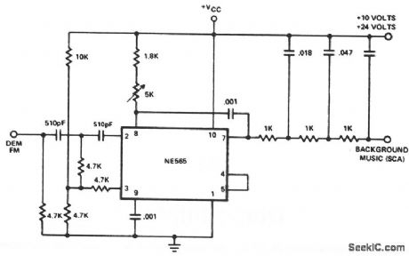
This application involves demodulation of a frequency-modulated subcarrier of the main channel. This popular example uses the PLL to recover the SCA (Subsidiary Carrier Authorization or storecast music) signal from the combined signal of many commercial FM broadcast stations. The SCA signal is a 67 kHz frequency-modulated subcarrier which puts it above the frequency spectrum of the normal stereo or monaural FM program material. By connecting the circuit to a point between the FM discriminator and the deemphasis filter of an FM receiver and tuning the receiver to a station which broadcasts an SCA signal, you can obtain hours of commercial-free background music. (View)
View full Circuit Diagram | Comments | Reading(1409)
ADJUSTABLE_DELAY
Published:2009/7/7 8:47:00 Author:May
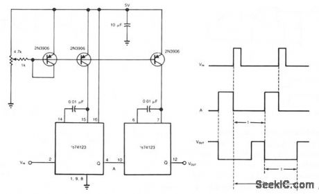

You can obtain well over 360 ° of phase delay by cascading two monostable multivibrators. In a typical configuration, a single monostable multivibrator is used to introduce delay in a pulse train; the multivibrator triggers on each incoming pulse, provided it resets in time for the next pulse. Yet even when it resets in time, the single monostable multivibrator provides a maximum phase delay of less than 360 °. However, with the cascaded-multivibrator approach, you can achieve 650 ° of phase delay by using an input-pulse spacing of 200 μs for example, with the component values shown. Every input pulse will trigger the circuit while you adjust the phase delay throughout its available range. The first multivibrator triggers the second one, whose reset marks the total delay time (2t). Each introduces a delay of t μs, based on 0.01-μF timing capacitors and equal charging currents from the three-transistor, dual-current source. The two multivibrator arrangement allows the first multivibrator to reset in time to be triggered by the next input pulse. Also, the variation of t is linear with the potentiometer setting. (View)
View full Circuit Diagram | Comments | Reading(1320)
Memory_core_sense_amplifier_using_an_MC1514
Published:2009/7/21 8:30:00 Author:Jessie
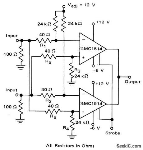
Memory core sense amplifier using an MC1514 (courtesy Motorola Semiconductor Products Inc.). (View)
View full Circuit Diagram | Comments | Reading(828)
TV_IF_amplifier_with_video_detector_and_sound_takeoff_using_dual_gate_MOSFETs
Published:2009/7/21 8:29:00 Author:Jessie

TV IF amplifier with video detector and sound takeoff using dual-gate MOSFETs (courtesy Texas Instruments Incorporated). (View)
View full Circuit Diagram | Comments | Reading(781)
Sequentially_addressed_8_channel_data_acquisition_subsystem_capable_of_acquiring_data_to_12_bit_accuracy_at_a_220_kHz_throughput_rate
Published:2009/7/21 8:29:00 Author:Jessie

Sequentially addressed 8-channel data acquisition subsystem capable of acquiring data to 12-bit accuracy at a 220 kHz throughput rate. The MPX-8A is a multiplexor, the SHA-2A a sample-and-hold amplifier and the ADC1103 a high-speed A/D converter (courtesy Analog Devices, Inc.). (View)
View full Circuit Diagram | Comments | Reading(847)
| Pages:982/2234 At 209819829839849859869879889899909919929939949959969979989991000Under 20 |
Circuit Categories
power supply circuit
Amplifier Circuit
Basic Circuit
LED and Light Circuit
Sensor Circuit
Signal Processing
Electrical Equipment Circuit
Control Circuit
Remote Control Circuit
A/D-D/A Converter Circuit
Audio Circuit
Measuring and Test Circuit
Communication Circuit
Computer-Related Circuit
555 Circuit
Automotive Circuit
Repairing Circuit