Amplifier Circuit
DIFFERENTIAL_INSTRUMENTATION_AMPLIFIER
Published:2009/7/7 9:09:00 Author:May | From:SeekIC

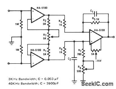
This circuit relies on extremely high input impedance for effective operation. The HA-5180 with its JFET input stage, performs well as a pre-amplifier. The standard three amplifier conftgura-tion is used with very close matching of the resistor ratios R5/R4 and (R1 + R8)/R6, to insure high common-mode rejection (CMR). The gain is con-trolled through fi3 and is equal to 2R1/R3. Additional gain can be had by increasing the ratios R5/R4 and (R7 + R8)/R6. The capacitors C1 and C2 improve the ac response by limiting the effects of transients and noise. Two suggested values are given for maximum transient suppression at fre-quencies of interest. Some of the faster DVM's are operating at peak sampling frequency of 3-kHz, hence the 4-kHz, low-pass time constant. The 40-kHz, low-pass time constant for ac voltage ranges is an arbitrary choice, but should be chosen to match the bandwidth of the other components in the sys-tem. C1 and C2 might however, reduce CMR for ac signals if not closely matched. Input impedances have also been added to provide adequate dc bias currents for the HA-5180 when open-circuited.
Reprinted Url Of This Article:
http://www.seekic.com/circuit_diagram/Amplifier_Circuit/DIFFERENTIAL_INSTRUMENTATION_AMPLIFIER.html
Print this Page | Comments | Reading(3)

Article Categories
power supply circuit
Amplifier Circuit
Basic Circuit
LED and Light Circuit
Sensor Circuit
Signal Processing
Electrical Equipment Circuit
Control Circuit
Remote Control Circuit
A/D-D/A Converter Circuit
Audio Circuit
Measuring and Test Circuit
Communication Circuit
Computer-Related Circuit
555 Circuit
Automotive Circuit
Repairing Circuit
Code: