
Circuit Diagram
Index 994
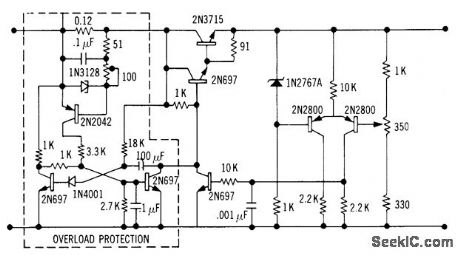
OVERLOAD_PROTECTION_WITH_RIPPLE_CLIPPING
Published:2009/7/21 10:15:00 Author:Jessie
Power transistor interrupts load when current exceeds safe limit, and also serves as part of ripple dipper.-J. J. Rado, Versatile SCR Protection for Power Supplies, EEE, 13:8, p 56-62. (View)
View full Circuit Diagram | Comments | Reading(678)
REVERSE_PHASE_PROTECTION
Published:2009/7/21 10:14:00 Author:Jessie
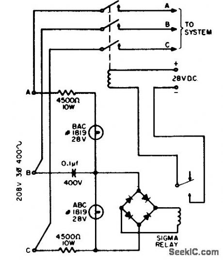
Used to protect navigation system against damage if phase rotation is reversed by careless or accidental power transfers. With correct rotation, lamp ABC lights and relay closes control circuit to allow operation. With reverse phase rotation, lamp BAC lights and relay does not close.-J. J. Pirch, Simple Reverse-Phase Protection, EEE, 11:12, p 26. (View)
View full Circuit Diagram | Comments | Reading(2716)
SERIES_REGULATOR_WITH_OVERLOAD_PROTECTION
Published:2009/7/21 10:13:00 Author:Jessie
Tunnel diode and transistor serve as overload sensing circuit used to trigger monostable mvbr, to protect series-pass transistors against overload. Circuit resets continuously after overload until trouble is cleared. Protection is adequate for resistive loads only.-J. Takesuye and H. Weber, Silicon Power Transistors Provide New Solutions to Voltage Control Problems, Motorola Application Note AN-163, Aug. 1965. (View)
View full Circuit Diagram | Comments | Reading(819)
AND_GATE_PROTECTS_FROM_VOLTAGE_FAILURE
Published:2009/7/21 10:11:00 Author:Jessie
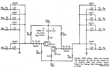
Deteuls absence of any one of several critical supply voltages of either polarity and energizes interlocking relay to prevent damage to components. Number of monitored circuits is limited by sum of leakage currents through 1N457 diodes. When this exceeds 100 microamp, Q1 and Q2 may remain on. –A. Shapiro, AND Gate Protects System Should the Voltage Fail, Electronics, 39:14, p 79-80. (View)
View full Circuit Diagram | Comments | Reading(861)
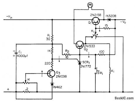
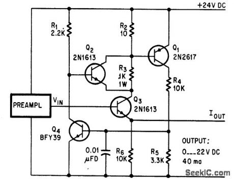
OVERLOAD_PROTECTION
Published:2009/7/21 10:09:00 Author:Jessie
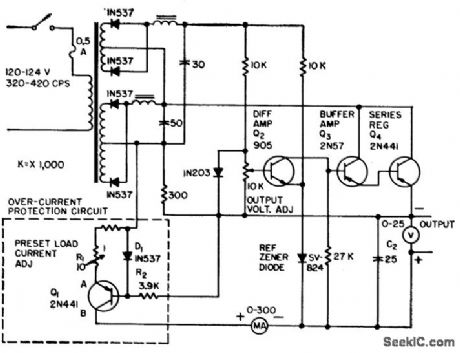
Transistor Q4 in conventional series regulated power supply is protected against charging current of load capacitance C2 by sharp current-limiting-characteristic protection circuit that operates statically, without need for resetting, in preset range of from 50 to 250 ma, and provides instantaneous response when regulator transistor is overloaded. Line regulation is 0.001% and load regulation is 0.002%.-H. D. Ervin, Transistor Power Supply has Overload Protection, Electronics, 31:25, p 74-75. (View)
View full Circuit Diagram | Comments | Reading(0)
MISSING_PULSE_DETECTOR
Published:2009/7/21 10:06:00 Author:Jessie
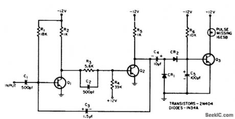
Turns on lamp if one of input pulses in continuous pulse input is missing. Pulses are very narrow (4 microsec wide) and 50 microsec apart for low duty cycle; Q1 and Q2 form pulse stretcher that increases widlh to about 40 microsec. In absence of stretched pulse, Q3 loses its bias and is turned on, making lamp light. -C. Gerston, Missing-Pulse Detector for Narrow Pulses, EEE, 12:8, p 72-74. (View)
View full Circuit Diagram | Comments | Reading(2)
STATE_GENERATOR_FOR_STEPPER
Published:2009/7/7 4:34:00 Author:May

Generates high-current square-wave pulses and provides correct switching sequence for exciting stepper motor when digital display is required to show instantaneous step angle and total revolutions traveled by shaft of stepper motor. If microprocessor is used, speed and direction of motor rotation can be controlled by programming period and level of output pulses. Clock signals trigger SN7473N JK flip-flop that changes ON/OFF states of four outputs as shown in table. Clock signal is obtained from external square-wave generator or from microprocessor such as KIM-1. Article also gives digital display circuit driven by same clock.-H. Lo, Digital Display of Stepper Motor Rotation, Computer Design, April 1978,p 147-148 and150-151 (View)
View full Circuit Diagram | Comments | Reading(773)
BUCK_BOOST_CONVERTER
Published:2009/7/7 4:32:00 Author:May


This converter can accommodate wide input-voltage swtngs,such as the 8 to 15-V swing typicalof a 12-V sealed lead/acid battery.The low batteryoutput indicates when mput voltage drops below 8V. Pulling shutdown turns off the circuit. (View)
View full Circuit Diagram | Comments | Reading(1050)
PROGRAMMABLE_VOLTAGE_CONTROLLED_TIMER
Published:2009/7/7 4:31:00 Author:May

The μA2240 may easily be configured as a programmable voltage controlled timer with a minimum number of external components. The modulation input (pin 12), which allows external adjustment of the input threshold level. A variable voltage is applied from the arm of a 10 k ohm potentiometer connected from VCC to ground. A change in the modulation input voltage will result in a change in the time base oscillator frequency and the period of the time base output (TBO). The TBO has an open-collector output that is connected to the regulator output via a 10 k ohm pull-up resistor. The output of the TBO drives the input to the 8-stage counter section.At start-up, a positive trigger pulse starts the TBO and sets all counter outputs to a low state. The binary outputs are open-collector stages that may be connected together to the 10 k ohm pull-up resistor to provide a wired-OR output function. This circuit may be used to generate 255 discrete time delays that are integer multiples of the time-base period. The total delay is the sum of the number of time-base periods, which is the binary sum of the Q outputs connected. Delays from 200 μs to 0.223 s are possible with this configuration. (View)
View full Circuit Diagram | Comments | Reading(742)
VOLTAGE_TO_PULSE_DURATION
Published:2009/7/7 4:31:00 Author:May
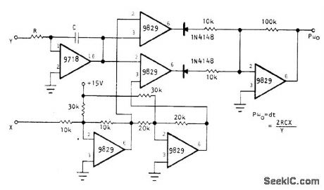
Optical Electronics 9829 opamps are used as fast comparators and 9718 FET opamp as fast integrator to give high precision at high speed for converting analog voltage to pulse duration for such applications as A/D conversion, delta code generation, motor speed control, and pulse-duration modulation. Output pulse durations can be as short as 1 μs. Conversion linearity is better than 0.1%. Minimum pulse duration is 100 ns, and maximum dynamic range is 40 dB. Reference voltages are determined by×input; if×is 3 V, reference voltages differ by 6 V. Two 9829 opamps present reference voltages to two com-parator opamps. Fifth 9829 sums comparator outputs and gives positive output.- Voltage to Pulse Width Converter, Optical Electronics, Tucson,AZ, Application Tip 10230. (View)
View full Circuit Diagram | Comments | Reading(1520)
80_METER_CWFOR_0RP
Published:2009/7/7 4:30:00 Author:May
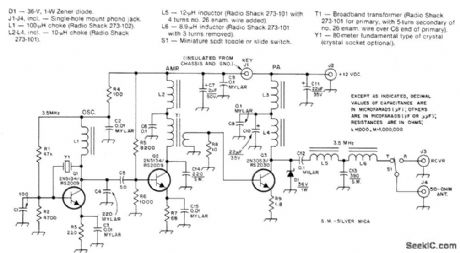
Low-powertransmit-tercan be mounted on small can for operation from separate 12-V supply. Zener D1 protects 03 by clamping on RF voltage peaks in excess of 36 V, Output tank of 03 gives satisfactory operation from 3.5 to 3.75 MHz without tuning.-D. DeMaw, Build This Sardine Sender, QST, Oct. 1978, p 15-17 and 38. (View)
View full Circuit Diagram | Comments | Reading(1330)
POSITIVE_TO_NEGATIVE_CONVERTER
Published:2009/7/7 4:29:00 Author:May
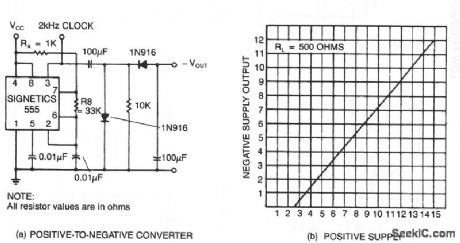
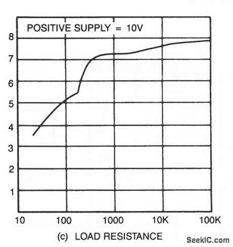

The transformerless dc-dc converter derives a negative supply voltage from a positive. As a bonus, the circuit also generates a clock signal. The negative output voltage tracks the dc-input voltage linearity (a), but its magnitude is about 3 V lower.Application of a 500- Ω load, (b), causes 10% change from the no-load value. (View)
View full Circuit Diagram | Comments | Reading(1023)
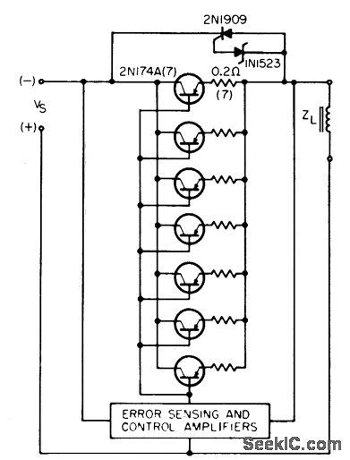
SHORT_CIRCUIT_PROOF_SHUNT_TYPE_SUPPLY_
Published:2009/7/21 10:52:00 Author:Jessie
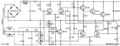
Output is variable from 1 to 17 V, maximum ripple is 1 mv peak-to-peak, and maximum current is 2.5 amp at 1 V or 0.8 amp at 17 V. After two hours of warmup, output drift is negligible (fraction of mv).-E. Baldinger and W. Czaja, Designing Highly Stable Transistor Power Supplies, Electronics, 32:39, p 70-73. (View)
View full Circuit Diagram | Comments | Reading(504)
PHASE_SEQUENCE_DETECTOR
Published:2009/7/7 4:28:00 Author:May


Circuit detects incorrect phase sequence of motor driving pump, compressor, conveyor, or other quipment that can be damaged by reverse rotation.Circuit also protects motor from phase loss that could cause rapid temperature rise and heat damage. LED is on when phasing is correct. For phase loss or incorrect sequence, output goes low and LED is dark. Diodes and zeners change sine waves for all phases to rectangular logiclevel pulses that feed gates. When phases are correct, output of G4 is train of rectangular pulses about 2.5 ns wide. Output is zero for incorrect sequences. Since leading edge of output pulse coincides with positive zero crossing of phase B, output pulses can be used to trigger SCR connected across phase B and driving relay-coil load. SCR then energizes relay only when sequence is correct.-H. Normet, Detector Protects 3.Phase-Powered Equipment, EDN Magazine, Aug. 5, 1978, p 78 and 80. (View)
View full Circuit Diagram | Comments | Reading(0)
TRANSISTOR_OVERVOLTAGE_FUSE
Published:2009/7/21 10:51:00 Author:Jessie
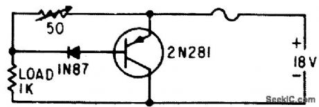
Proteclive circuit uses one resistor, one diode, amd one transistor. Transistor across supply line is cut off by 1N87 diode until overload occurs. When transistor conducts, fuse is open by current that would ordinarily destroy transistors being protected (represented here by 1K load).-K. Redmond, Low-Cost Transistor Overload Safety Circuit, Electronics, 33:42, p 102. (View)
View full Circuit Diagram | Comments | Reading(583)
ELECTRONIC_FUSE
Published:2009/7/21 10:50:00 Author:Jessie
Switches high series resistance R3 into circuit only when overload or short-circuit occurs. R3 is shunted out of load R2 by Q2,-L. Payerl, Overload Protection for D-C Amplifier, Electronics, 39:7, p 91. (View)
View full Circuit Diagram | Comments | Reading(7)
ZENER_GATED_SCR_PROTECTS_POWER_TRANSISTORS
Published:2009/7/21 10:49:00 Author:Jessie
Scr serves as controllable short-circuit across power transistors. Reaction time is about 2 microsec.-C. A. Blanchard, Zener-Gated SCR Protection for Power Transistors, EEE, 14:5, p 117-118. (View)
View full Circuit Diagram | Comments | Reading(723)
20_METER_VFO
Published:2009/7/7 4:26:00 Author:May

Tunes from 14.0 to 14.2 MHz、using stable Vackar design, Protective diode CR1 canbe any silicon rectifier Clamping diode CR3 improves stability by preventing conduction in gate of JFET osciliator Q1,-C,E,Galbreath、Low-Power Solid-State VFO Transmit-ter for 20 Meters,Ham Radio. Nov,1973, p 6-11 (View)
View full Circuit Diagram | Comments | Reading(1095)
SHORT_CIRCUIT_DETECTOR
Published:2009/7/21 10:48:00 Author:Jessie
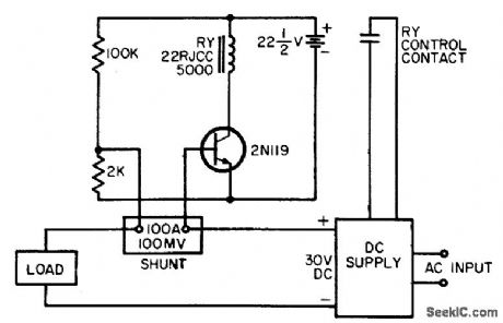
Shunt used in d-c power circuit for metering also serves here to drive base of transistor that senses over-loads. Relay in transistor circuit disconnects d-c power when drop ccross 100-mv shunt approaches 400 mv (4 times normal load current).-J. J. Pirch, Single-Transistor Short-Circuit Detector, EEE, 12:16, p 64. (View)
View full Circuit Diagram | Comments | Reading(1041)
DIGITAL_TO_FREQUENCY
Published:2009/7/7 4:26:00 Author:May

Combination of multiplying DAC and 556 dual timer provides complementary output frequencies under con trol of digital input. Opamp and diode types are not critical. Output frequency of each timer depends on supply voltages, capacitor values,and setting of R1.-J. Wilson and J. Whitmore,MDAC's Open Up a New World of Digital-Control Applications,EDN Magazine,Sept.20、1978、p 97-105. (View)
View full Circuit Diagram | Comments | Reading(794)
| Pages:994/2234 At 209819829839849859869879889899909919929939949959969979989991000Under 20 |
Circuit Categories
power supply circuit
Amplifier Circuit
Basic Circuit
LED and Light Circuit
Sensor Circuit
Signal Processing
Electrical Equipment Circuit
Control Circuit
Remote Control Circuit
A/D-D/A Converter Circuit
Audio Circuit
Measuring and Test Circuit
Communication Circuit
Computer-Related Circuit
555 Circuit
Automotive Circuit
Repairing Circuit