
Circuit Diagram
Index 981
2185_MC_MARINE_BAND_TRANSMITTER
Published:2009/7/21 7:48:00 Author:Jessie
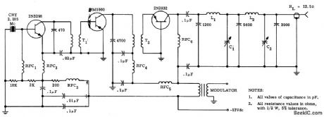
Grounded-base Colpitts oscillator uses series-mode crystal with driver and output stage. Current drain is only 1.5 amp from storage battery. No converter is required. Output is 13-w rms carrier.-R. J. Brubaker, An All. Solid-State Marine Band Transmitter, Motorola Application Note AN-156, Feb. 1966. (View)
View full Circuit Diagram | Comments | Reading(637)
Simple_full_wave_power_control_circuit_using_a_triac
Published:2009/7/21 7:48:00 Author:Jessie

Simple full-wave power control circuit using a triac (courtesy Motorola Semiconductor Products Inc.). (View)
View full Circuit Diagram | Comments | Reading(750)
Color_TV_358_MHz_crystal_oscillator_using_adual_gate_MOSFET
Published:2009/7/21 7:47:00 Author:Jessie

Color TV 3.58 MHz crystal oscillator using adual-gate MOSFET (courtesy Texas Instruments Incorporated). (View)
View full Circuit Diagram | Comments | Reading(893)
Simple_DC_power_control_circuit_using_an_SCR
Published:2009/7/21 7:47:00 Author:Jessie

Simple DC power control circuit using an SCR (courtesy Motorola Semiconductor Products Inc.). (View)
View full Circuit Diagram | Comments | Reading(1044)
STEPPED_FREQUENCY_EXCITER
Published:2009/7/21 7:47:00 Author:Jessie
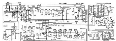
Provides crystal-controlled output frequency in 100-kc steps at 1-sec intervals from 31.05 to 54.95 Mc, with each step an odd multiple of 50 kc. Used to control pulse transmitter and receiver at widely separated locations, for observation of mutual propagation conditions between the two points. Frequency control of r-f oscillator is obtained by mixing sample r-f signal with 1-Mc reference and comparing components of product with 50-kc pulse spectrum supplied by pulse generator V6B.-Frequency Stepper for Radio Propagation Tests, Electronics, 32:4, p 44-46. (View)
View full Circuit Diagram | Comments | Reading(621)
TV_vertical_deflection_system
Published:2009/7/21 7:46:00 Author:Jessie

TV vertical deflection system (courtesy GTE Sylvania Incorporated). (View)
View full Circuit Diagram | Comments | Reading(773)
Full_wave_average_voltage_feedback_control_circuit_for_a_600_watt_load
Published:2009/7/21 7:46:00 Author:Jessie
Full-wave average voltage feedback control circuit for a 600-watt load (courtesy Motorola Semiconductor Products Inc.). (View)
View full Circuit Diagram | Comments | Reading(587)
PUSH_PUSH_OUTPUT_DOUBLER
Published:2009/7/21 7:45:00 Author:Jessie

Input is conventional push-pull configuration providing out-of-phase signals for both transistors, but for output circuit both transistors operate in parallel into standard pi network. This cancels fundamental and odd-order harmonics, leaving only second harmonic predominating in output circuit. Transistors can be 2N1692.-W. A. Rheinfelder, Choosing the Best Transmitter Output Stage, EEE, 11:10, p 48-53.
(View)
View full Circuit Diagram | Comments | Reading(992)
240_volt_triac_control_circuit_driven_by_two_MOC3011_optically_coupled_tdac_drivers
Published:2009/7/21 7:59:00 Author:Jessie

240-volt triac control circuit driven by two MOC3011 optically coupled tdac drivers (courtesy Motorola Semiconductor Products Inc.).
(View)
View full Circuit Diagram | Comments | Reading(956)
PULSER_FOR_250_KW_MODULATOR
Published:2009/7/21 7:59:00 Author:Jessie

Trigger generator for scr modulator uses, two-layer and four-layer diodes to provide pulse burst, repetition rates up to 25 kc.-H.G. Heard, Controlled Rectifier Produces Quarter-Megatwatt Pulse Power, Electronics, 34:25, P 54-55. (View)
View full Circuit Diagram | Comments | Reading(632)
Complete_FM_TV_45_MHz_sound_channel_using_an_ECG1045_14_pin_DIP
Published:2009/7/21 7:57:00 Author:Jessie

Complete FM/TV 4.5 MHz sound channel using an ECG1045 14-pin DIP. Audio power output is 1.5 watts. The ECG1045 contains a three-state high-gain directional IF amplifier and a ratio detector. IF transformers and the AF output transformer are standard items and can be purchased at Radio Shack. This circuit can be modified for 10.7 MHz operation by selecting the proper IF transformers (courtesy GTE Sylvania Incorporated). (View)
View full Circuit Diagram | Comments | Reading(901)
RMS_open_loop_voltage_compensator_regulator_for_small_conduction_angles
Published:2009/7/21 7:57:00 Author:Jessie
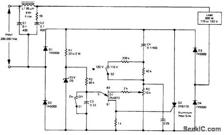
RMSopen-loop voltage compensator (regulator) for small conduction angles. This circuit provides an output of 110/115 ±2.5 volts at 600 watts for an input of 200 to 260 volts. This circuit is suitable for applications requiring a conduction angle of less than 90 (courtesy Motorola Semiconductor Products Inc.). (View)
View full Circuit Diagram | Comments | Reading(478)
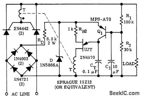
DUAL_PULSE_TRIGGER
Published:2009/7/21 7:57:00 Author:Jessie
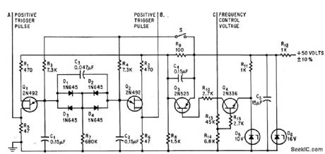
Dual triggers supply alternating pulses for driving d-c to d-c voltage converter connected to A and B. Frequency of triggering can be adjusted from 650 to 900 cps by varying base-to-base voltages of unijunction transistors.-T. Wilson, Voltage Controls Dual-Pulse SCR Trigger, Electronics, 37:28, p 62-63. (View)
View full Circuit Diagram | Comments | Reading(618)
Proportional_controller_for_heater_using_two_op_amps
Published:2009/7/21 7:56:00 Author:Jessie
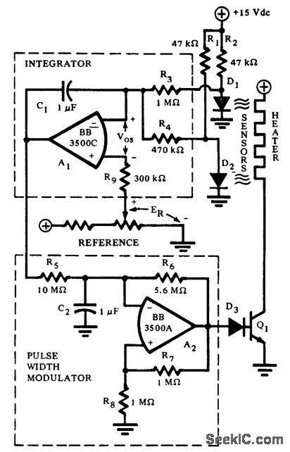
Proportional controller for heater using two op amps. The integrating error amplifier holds the heater current pulse width at a sustaining value at equilibrium (courtesy Burr-Brown Research Corporation). (View)
View full Circuit Diagram | Comments | Reading(627)
INPUT_TURNS_BOTH_TRANSISTORS_ON
Published:2009/7/21 7:55:00 Author:Jessie
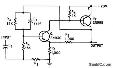
Unlike Schmitt trigger, both transistors stop conduction when input is removed.-L. L. Kleinberg, Complementary Shaper Replaces Schmitt Trigger, Electronics, 37:26, p 66. (View)
View full Circuit Diagram | Comments | Reading(668)
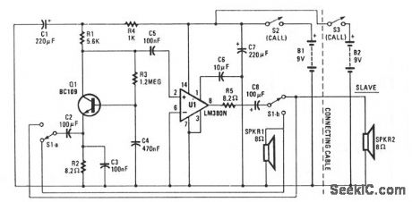
TWO_WAY_INTERCOM
Published:2009/7/7 9:29:00 Author:May
View full Circuit Diagram | Comments | Reading(773)
HANDS_OFF_INTERCOM
Published:2009/7/7 9:27:00 Author:May
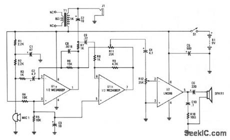
Amplifier A increases the microphone's output to a usable level. The output signal is fed to op amp B, which inverts the signal 180°. A balance-control potentiometer connects across the outputs of amplifiers A and B. If an audio tone is fed into the microphone and the balance potentiometer's wiper is all the way over to the A output position, the tone will be heard at a high level. As the wiper is rotated toward the B output, the audio level will decrease until it just about disappears near the center of the potentiometer's range. As you continue to rotate the wiper, the signal will begin to increase once again.With the balance control set for a minimal output, the intercom's tendency to self-oscillate from acoustical feedback between the microphone and speaker is kept to a minimum. The microphone's ampli-fted signal at A's output is fed to the other intercom through the audio in/out cable. Since both intercom units are alike, the audio information coming from one unit feeds the other at the input of op amp B. The incoming audio is amplified slightly by op amp B and the output signal is sufficiently increased by the power amp to drive the speaker. (View)
View full Circuit Diagram | Comments | Reading(1096)
INTERCOM
Published:2009/7/7 9:25:00 Author:May
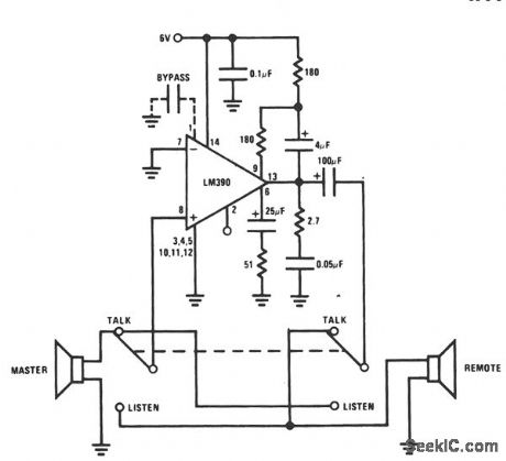
This intercom uses a single audio IC as a two-way amplifier, and the speakers as microphones. A single 6-V supply provides adequate audio volume. (View)
View full Circuit Diagram | Comments | Reading(0)
BIDIRECTIONAL_INTERCOM_SYSTEM
Published:2009/7/7 9:24:00 Author:May

This system uses μA759 audio IC devices and a common connection between the preamps as an inter-connect. Either mike can drive either speaker. Duplex operation is possible with only one cable (two wires). (View)
View full Circuit Diagram | Comments | Reading(825)
PERSONAL_POCKET_PAGER
Published:2009/7/7 9:21:00 Author:May
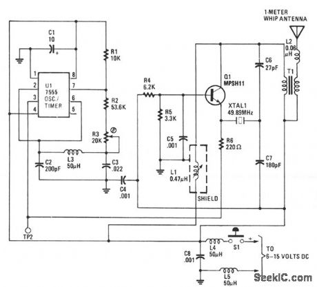
When activated, the transmitter sends out a 49.890-MHz, AM rf carrier. The receiver detects, ampli-fies, and decodes the rf signal, which, in turn, activates a piezo buzzer. The receiver is small enough to carry in a pocket or sit on your workbench, The transmitter is also small and fits easily into a pocket for quick access. (View)
View full Circuit Diagram | Comments | Reading(715)
| Pages:981/2234 At 209819829839849859869879889899909919929939949959969979989991000Under 20 |
Circuit Categories
power supply circuit
Amplifier Circuit
Basic Circuit
LED and Light Circuit
Sensor Circuit
Signal Processing
Electrical Equipment Circuit
Control Circuit
Remote Control Circuit
A/D-D/A Converter Circuit
Audio Circuit
Measuring and Test Circuit
Communication Circuit
Computer-Related Circuit
555 Circuit
Automotive Circuit
Repairing Circuit