© 2008-2012 SeekIC.com Corp.All Rights Reserved.
power supply circuit
SECOND_AUDIO_PROGRAM_ADAPTER
Published:2009/7/7 8:02:00 Author:May | From:SeekIC

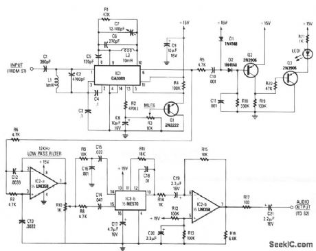
The baseband-audio input comes from the pole of switch S1 in the stereo decoder, and is coupled to IC1 (a CA3089) via a 78.6 kHz bandpass filter that consists of capacitors C1 and C2, and inductor L1. IC1 is a combination i-f amplifier and quadrature detector normally used for FM radio systems operating within an i-f of 10.7 MHz. The device works equally well at 78.6 kHz. Capacitors C6 and C7, and inductor L2 tune the detector section to 78.6 kHz, while C5 provides the necessary 90-degree phase shift for proper quadrature detector operation. The output voltage at pin 13 of IC1 is proportional to the level of the incom-ing signal. When the voltage at the wiper of potentiometer R3 reaches a predetermined threshold level, Q1 conducts, grounding pin 5 of IC1, enabling 101's mute function.
Detected audio output from pin 6 of IC1 goes to IC2a, which is configured as a 12-kHz, -12 dB per octave, low-pass filter. The output of IC2a appears across potentiometer R10, which provides a means of adjusting the drive level into IC3b, the 2:1 compander.
Audio from the wiper of R10 is split into two paths: a high-pass filter (C14 and R8) provides a path to the rectifier input of the compander, and a bandpass filter (R9, C16, and C15) that feeds the audio input of the compander. A fixed 390-μs de-emphasis network is formed by C18 and R11 in conjunction with IC3b, Corrected audio appears at pin 10 of IC3b and is coupled to IC2b, and output buffer amplifier.
Audio from pin 6 of IC1 is also coupled to an audio high-pass filter, R5 and C10, and fed to an audio rectifier, D1, D2, and C11. When a SAP signal is detected by IC1, it is rectified by D1 and D2; the resultant dc charges C11. An increasing positive voltage at the base of Q2 causes its current flow to decrease, so the voltage at Q2's collector also decreases. That in turn causes the base voltage of Q3 to drop, which causes Q3 to conduct, thereby lighting the LED.
Reprinted Url Of This Article:
http://www.seekic.com/circuit_diagram/Power_Supply_Circuit/SECOND_AUDIO_PROGRAM_ADAPTER.html
Print this Page | Comments | Reading(3)

Article Categories
power supply circuit
Amplifier Circuit
Basic Circuit
LED and Light Circuit
Sensor Circuit
Signal Processing
Electrical Equipment Circuit
Control Circuit
Remote Control Circuit
A/D-D/A Converter Circuit
Audio Circuit
Measuring and Test Circuit
Communication Circuit
Computer-Related Circuit
555 Circuit
Automotive Circuit
Repairing Circuit
New published articles
Response in 12 hours

Code: