Basic Circuit
SPEED_CONTROL_FOR_INDUCTION_MOTOR
Published:2009/7/7 3:40:00 Author:May | From:SeekIC

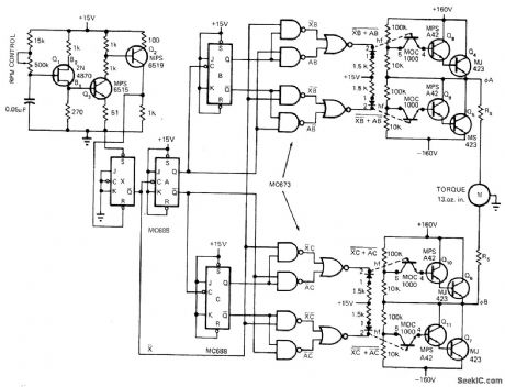
Uses UJT oscillator Q1 to generate frequency in range from 40 to 1200 Hz for feeding to divide-by-4 configuration that gives motor source frequency range of 10 to 300 Hz. With induction motor having two pairs of poles, this gives theoretical speed range of 300 to 9000 rpm with essentially constant torque. Speed varies linearly with frequency. Circuit uses pair of flip-flops (MC673) operated in time-quadrature to perform same function as phase-shifting capacitor so motor receives two drive signals 90° apart. Article covers operation of circuit in detail. Optoisolators are used to provide bipolar drive signals from unipolar control signals. Each output drive circuit is normally off and is turned on only when its LED is on. If logic power fails, drives are disabled and motor is turned off as fail-safe feature.-T. Mazur, Unique Semiconductor Mix Controls Induction Motor Speed, EDN Magazine, Nov. 1, 1972, p28-31.
Reprinted Url Of This Article:
http://www.seekic.com/circuit_diagram/Basic_Circuit/SPEED_CONTROL_FOR_INDUCTION_MOTOR.html
Print this Page | Comments | Reading(3)

Article Categories
power supply circuit
Amplifier Circuit
Basic Circuit
LED and Light Circuit
Sensor Circuit
Signal Processing
Electrical Equipment Circuit
Control Circuit
Remote Control Circuit
A/D-D/A Converter Circuit
Audio Circuit
Measuring and Test Circuit
Communication Circuit
Computer-Related Circuit
555 Circuit
Automotive Circuit
Repairing Circuit
Code: