
Circuit Diagram
Index 337
Acousto-Optic dual-controlled high - power lantern accompanied by birdsong circuit using SH805
Published:2012/9/13 2:02:00 Author:Ecco | Keyword: Acousto-Optic, dual- controlled , high - power , lantern , accompanied by birdsong

As shown in the diagram, the circuit consists of voice control circuit, Acousto-Optic dual control monostable timing circuit, SH805 lighting control circuit, birdsong voice circuit and AC buck rectifier circuit and other components. It can realize manual or automatic control of four high-power lantern with 16 kinds lantern patterns changing, but also sending sweet birdsong. BM is sound energy sensor; BH-SK-I is the voice control ASIC.
(View)
View full Circuit Diagram | Comments | Reading(701)
Computer room temperature control circuit using TC620 temperature sensor
Published:2012/9/13 1:44:00 Author:Ecco | Keyword: Computer room , temperature control , temperature sensor

As shown in the figure, the circuit consists of the temperature sensor, control devices, the upper and lower temperature display, relay control motor circuit, waves analog voice circuit and AC buck rectifier circuit.
(View)
View full Circuit Diagram | Comments | Reading(1609)
5 Watt UHF TV Linear amplifier
Published:2012/9/12 21:17:00 Author:Ecco | Keyword: 5 Watt , UHF , TV Linear amplifier

This small circuit is a Linear amplifier for driving small UHF TV transmitters. Its gain is 7dB and can amplify a signal between 450-800 MHz. You can drive the circuit with 1 to 1,5 Watts signal. Better use double layer PCB with the second layer connected to earth. Use a stabilized power supply 25 volts and at least 5Amps.
Source: NEXT.GR (View)
View full Circuit Diagram | Comments | Reading(1508)
4Watt UHF TV linear amplifier
Published:2012/9/12 21:17:00 Author:Ecco | Keyword: 4Watt , UHF TV , linear amplifier

That Circuit is a UHF TV linear amplifier for small TV transmitters with output aroun 100-200mW. The transistor BGQ136 comes with SOT-122 case has gain of 13dB at 800MHz. So with input 100mW you get 2W output and for 200mW you get 4W.
Source: NEXT.GR (View)
View full Circuit Diagram | Comments | Reading(1992)
Advanced bicycle lighting Schematic
Published:2012/9/12 21:16:00 Author:Ecco | Keyword: Advanced, bicycle lighting
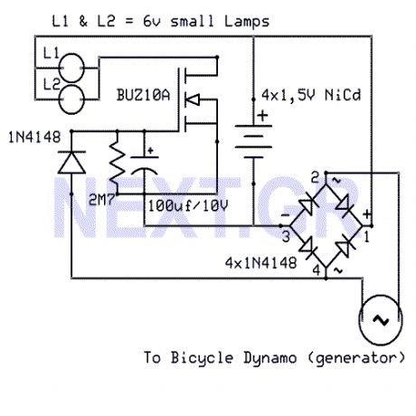
That Circuit is an advanced bicycle lighting system which will power your lights and also charge four NiCd batteries while you running in the streets, for keeping the lights on while the bicycle is stoped. Its fully automated without any switches.
Source: NEXT.GR (View)
View full Circuit Diagram | Comments | Reading(1707)
Antenna tunning circuit for 27MHz CB band
Published:2012/9/12 21:13:00 Author:Ecco | Keyword: Antenna tunning, 27MHz CB band
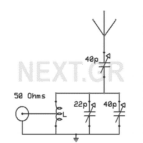
The antenna tunning circuit can accommodate 1/2 wave length antennas or higher, for input resistances of 50 Ohms which make it suitable for CB (Citizen Band) transceivers. C1 is for fine tunning and C2 is just for tunning. Turning C3 with the help of C2 you can set the SWR to 1:1. The Coil L is made of 11 turns of insulated copper wire with diameter of 1mm.
Source: NEXT.GR (View)
View full Circuit Diagram | Comments | Reading(1373)
Sound effects generator (UM3561)
Published:2012/9/12 21:10:00 Author:Ecco | Keyword: Sound effects generator
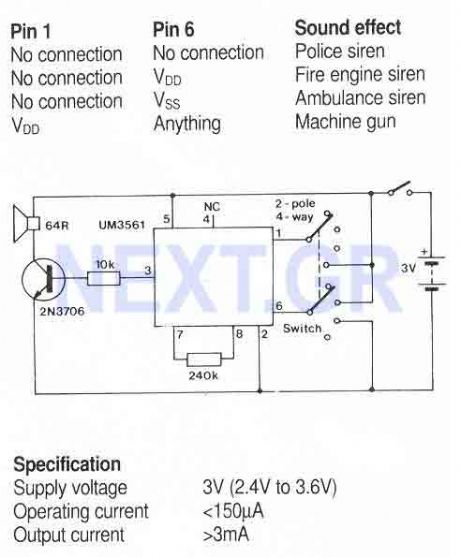
A simple sound generator IC that can produce four sound effects. Designed for use in toys, the effects are selected by varying the connections to pins1 and 6 as follows... (View)
View full Circuit Diagram | Comments | Reading(788)
Temperature Controller with U217B
Published:2012/9/12 21:09:00 Author:Ecco | Keyword: Temperature Controller

A triac controller for switching resistive loads directly from the mains supply using the zero crossing technique. The device is powered directly from the mains via a diode and dropper resistor, and the IC has its own regulator to limit its supply to 9.25V. To ensure that no switching occurs outside of the zero crossing point, full wave logic is employed to guarantee that complete mains cycles only are switched to the load.
Source: NEXT.GR (View)
View full Circuit Diagram | Comments | Reading(1370)
Fluid Level Detector (LM1830N)
Published:2012/9/12 21:08:00 Author:Ecco | Keyword: Fluid Level, Detector
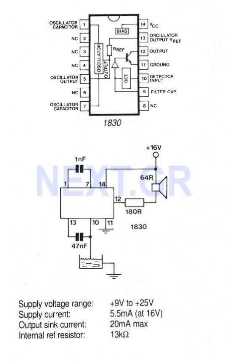
The IC is ideal for detecting the presence, absence or level of water or other conducting liquids. A detector determines the presence or absence of fluid by comparing the resistance of the fluid with the IC's internal reference resistance. An AC signal is used to prevent plating of the probe. When the probe resistance increases the loudspeaker will emit a 500Hz tone.
Source: NEXT.GR (View)
View full Circuit Diagram | Comments | Reading(1126)
Fast charge Controller with MAX712 / MAX713
Published:2012/9/12 21:07:00 Author:Ecco | Keyword: Fast charge Controller

The MAX712 and MAX713 are nickel cadmium (Ni-Cd) battery fast charge controllers which will fast charge batteries from a DC source at least 1V higher than the maximum battery voltage. 1 to 16 series cells can be charged at rates up to 4C. A voltage-slope detecting analogue-to-digital converter, timer, and temperature window comparator determine charge completion. The MAX712 or 713 are powered by the DC source via an on-clip +5V shunt regulator, and draw a maximum of 5uA from the battery when not charging. A low-side current-sense resistor allows the battery charge current to be regulated while still supplying the power to the battery's load.
Source: NEXT.GR (View)
View full Circuit Diagram | Comments | Reading(2208)
Humidity Sensor with the H14DL
Published:2012/9/12 21:04:00 Author:Ecco | Keyword: Humidity Sensor
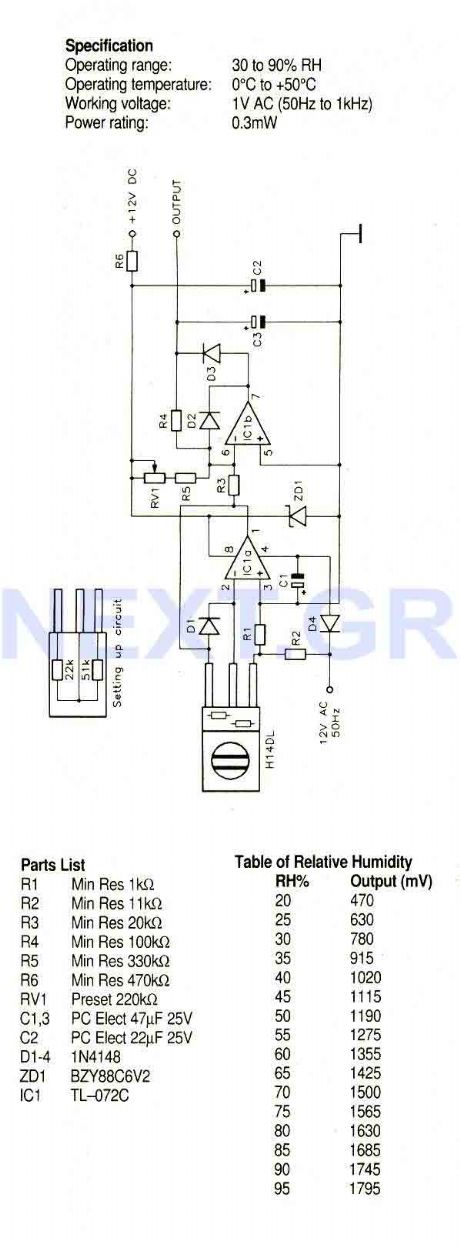
A humidity sensor with temperature compensation built-in. Never apply a DC voltage to the sensor, even measuring the sensor with an ohmmeter will damage the device, always ensure that an AC voltage is applied. Avoid condensation, freezing, dust, mist, oil, alcohol, etc. To set up this circuit replace the H14DL with Min Res 22Kohm and Min Res 51Kohm as shown, Acjust RV1 until a voltmeter between output and ground reads 1.40V.
Source: NEXT.GR (View)
View full Circuit Diagram | Comments | Reading(1281)
Light to Frequency Converter TSL220
Published:2012/9/12 21:04:00 Author:Ecco | Keyword: Light to Frequency, Converter

A large area photodiode and current to frequency converter combined in a clear plastic 8-pin DIL package. The output is a pulse train whose frequency is directly proportional to the light intensity. The output is CMOS compatible (use a 3k3 pulldown resistor to drive LS TTL) and the frequency can be measured by pulse counting, period timing or integration techniques. The photodiode has a wide dynamic range, high sensitivity and high noise immunity.
Source: NEXT.GR (View)
View full Circuit Diagram | Comments | Reading(1070)
Remote control Encoder M145026B-1
Published:2012/9/12 21:03:00 Author:Ecco | Keyword: Remote control Encoder
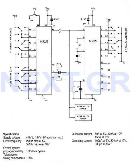
This encoder can generate up to 19,683 codes from 9 address lines by detecting 1,0, or open circuit. To initiate the transmit sequence, pin 14 should be pulsed low. The encoder will now output on pin 15 a data stream representing the condition on each of the address/data pins in turn and then repeat the operation, so that two complete identical words are transmitted. If pin 14 is held low, the output will be continuous, otherwise two identical words are output for each pulse on pin 14. A 1 is transmitted as two long pulses, a 0 as two short pulses, and an open circuit as a long pulse followed by a short pulse.
Source: NEXT.GR (View)
View full Circuit Diagram | Comments | Reading(3267)
Multi-Instrument Melody Generator UM34811A
Published:2012/9/12 21:02:00 Author:Ecco | Keyword: Multi-Instrument, Melody Generator

This circuit is based on a preprogrammed multi-instrument melody generator IC, containing a 512-note memory capable of generating 16 tunes. The comprehensive control facilities enable playing - all tunes repeatedly or stopping at the end, - or one tune repeatedly or stopping at the end.
Source: NEXT.GR (View)
View full Circuit Diagram | Comments | Reading(1143)
Voltage Controlled Filter SSM2044P
Published:2012/9/12 21:01:00 Author:Ecco | Keyword: Voltage Controlled Filter

At this circuit the SSM2044 IC is used, a 4 pole voltage controlled filter designed for electronic music applications. On-chip voltage control of resonance allows direct and easy interfacing with programmers and controllers. The IC features extended control range, low noise, and high control rejection. The filter can also be used as a low distortion sinewave oscillator.
Source: NEXT.GR (View)
View full Circuit Diagram | Comments | Reading(1168)
Waveform Generator with ICL 8038CCPD
Published:2012/9/12 21:01:00 Author:Ecco | Keyword: Waveform Generator , ICL

That circuit is based on a 14-pin DIL IC capable of producing sine, square, triangular, sawtooth and pulse waveforms of high accuracy and stability. The frequency may be selected to be from 0.001Hz to 1Mhz, Frequency modulation and sweeping can be accomplished with an external voltage and the frequency can be programmed digitally by resistors or capacitors. Sweep range can be up to 40:1 or 1000:1 with a little less quality.
Source: NEXT.GR (View)
View full Circuit Diagram | Comments | Reading(1649)
Video speed 6-bit Flash A/D converter
Published:2012/9/12 21:00:00 Author:Ecco | Keyword: Video speed , 6-bit, Flash, A/D converter

This circuit use the CA3306 a family of CMOS parallel (flash) analogue to digital converters designed for low power, high speed applications. The CA3306CE operates at sampling rates up to 10 million samples per second and the CA3306E up to 15 million samples per second permitting analogue signals with bandwidths up to 5MHz or 7.5MHz to be fully digitised to 6-bit accuracy.
Source: NEXT.GR (View)
View full Circuit Diagram | Comments | Reading(1301)
FM radio with TDA7000
Published:2012/9/12 20:59:00 Author:Ecco | Keyword: FM radio
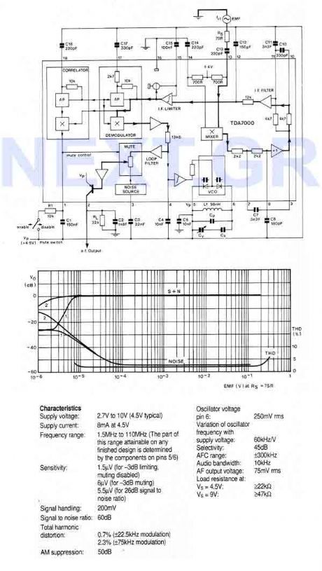
An FM radio on a single chip requiring only a few simple peripheral components. In particular the ship requires only one simple coil and alignment is very easy. The chip includes an RF input stage, mixer, local oscillator, IF amplifier/limiter, phase demodulator, mute detector and mute switch. The output will directly drive a crystal earpiece or could be used with a TBA820M to form a complete portable radio.
Source: NEXT.GR (View)
View full Circuit Diagram | Comments | Reading(2)
22 Watt power amplifier with TDA2040V
Published:2012/9/12 20:57:00 Author:Ecco | Keyword: 22 Watt , power amplifier

This circuit uses the TDA2040V which is a monolithic power amplifier IC intended for use as a high quality, class AB audio power amplifier. Typically it provides 22W output power into 4ohm with 0.5% distortion, from 32V supply. The device is designed to operate from a split power supply and no electrical isolation is needed between the mounting tab and its heatsink. It provides a high output current and has very low harmonic and crossover distortion.
Source: NEXT.GR (View)
View full Circuit Diagram | Comments | Reading(831)
2 Watt stereo amplifier with LM1877N-9
Published:2012/9/12 20:57:00 Author:Ecco | Keyword: 2 Watt, stereo amplifier

This circuit uses a stereo amplifier IC in a 14-pin DIL package that requires very few external components to make a complete 2 Watt per channel power amplifier. (View)
View full Circuit Diagram | Comments | Reading(2203)
| Pages:337/2234 At 20321322323324325326327328329330331332333334335336337338339340Under 20 |
Circuit Categories
power supply circuit
Amplifier Circuit
Basic Circuit
LED and Light Circuit
Sensor Circuit
Signal Processing
Electrical Equipment Circuit
Control Circuit
Remote Control Circuit
A/D-D/A Converter Circuit
Audio Circuit
Measuring and Test Circuit
Communication Circuit
Computer-Related Circuit
555 Circuit
Automotive Circuit
Repairing Circuit