
Circuit Diagram
Index 331
Third-order asymmetric filter circuit
Published:2012/9/17 1:34:00 Author:Ecco | Keyword: Third-order , asymmetric, filter

In the figure, thethird-order asymmetric filter has two ways of output UA1 and UA2, the former is high-pass filter output, and the later is the low-pass filter output.
(View)
View full Circuit Diagram | Comments | Reading(839)
Single-phase full-wave rectifier Π filter circuit
Published:2012/9/13 22:39:00 Author:Ecco | Keyword: Single-phase, full-wave, rectifier, Π filter

Typically, under the case with low current of the rectifier circuit (several tens mA ) , it may use resistor R with appropriate power, and can reduce the weight of the filter to reduce costs. The circuit is shown in the diagram.
(View)
View full Circuit Diagram | Comments | Reading(1784)
DC motor start circuit controlled by counter electromotive force
Published:2012/9/17 1:39:00 Author:Ecco | Keyword: DC motor start , counter electromotive force

When breaker QF is closed, pressing the start button ST will make DC contactor KM pull in, the motor M connected to R1 , R2, R3 in series is started. With the speed increaseing, the counter electromotive force increases, the voltage at both ends of the motor M is increased gradually, so that 1KM, 2KM, 3KM operate in an order, the main contacts will sequentially shorting connect R1, R2, R3, and finally the motor M is put into full pressure operation. 1KM, 2KM, 3KM are DC contactors, the pull-in coil's rated voltage must meet U1KM < U2KM < U3KM.
(View)
View full Circuit Diagram | Comments | Reading(1325)
The overtemperature sprinkler cooling device circuit for menagerie building
Published:2012/9/17 1:44:00 Author:Ecco | Keyword: overtemperature sprinkler , cooling , menagerie building

The circuit is shown as the figure. It consists of temperature detecting circuit, voltage comparator circuit, power switch circuit, croak sound circuit, AC buck rectifier circuit and other components. When indoor temperature is more than 32℃ in summer, it can automatically start the sprinkler to cool temperature. When the room temperature falls below a predetermined temperature, it stops the sprinkler. The circuit is suitable for the breeding of rare birds and animals, the circuit is simple with reliable performance. When the sprinkler works, it also issued the acoustic sound of frogs calling to attract to the attention of the personnel on duty.
(View)
View full Circuit Diagram | Comments | Reading(891)
Automatic thermostat with birds sound circuit
Published:2012/9/14 2:04:00 Author:Ecco | Keyword: Automatic thermostat , birds sound

The circuit is shown in Figure, and it consists of thermal sensor head, monostable trigger circuit, birdsong sounding circuit and AC buck rectifier circuit. It enables the electric apparatus and the storage to keep in a set temperature range, when the temperature is lower than the minimum temperature because of the heat leaving from apparatus, the heater is automatically turned on for heating with several birdsong.
(View)
View full Circuit Diagram | Comments | Reading(1167)
Auto - primary and secondary windings different voltage buck governor circuit
Published:2012/9/14 1:58:00 Author:Ecco | Keyword: Auto - primary , secondary windings , different voltage buck , governor
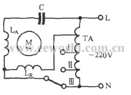
As shown in the diagram, the autotransformer TA is applied to the main and auxiliary winding LR to LA with different voltages for Buck governor. It uses autotransformer TA Buck governor to improve the motor start-up performance and power consumption. The disadvantage is that the autotransformer increases the whole volume and cost.
(View)
View full Circuit Diagram | Comments | Reading(565)
DC separately excited motor commutation circuit
Published:2012/9/13 22:34:00 Author:Ecco | Keyword: DC separately excited , motor , commutation
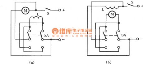
Therotation direction of the DC motor is determined by the direction of current in the field and windings, the field direction of the magnetic field is determined by the direction of excitation windingcurrent. In the diagram (a), switching switch SA can change the positive and negative electrode connection of excitation coil (winding) L, while the polarity of the power keeps constant, it can change the rotation direction of the motor. In the diagram (b), it can use SA to change the polarity of power's two ends, and the polarity of the magnetic coil keeps constant, and it can also achieve reversible steering. If the polarity of the excitation coil and the power is changed at the same time, the direction of generated magnetic field will not change, so the direction of rotation will maintain.
(View)
View full Circuit Diagram | Comments | Reading(1020)
Change-over switch selecting operating mode circuit
Published:2012/9/14 1:41:00 Author:Ecco | Keyword: Change-over switch , selecting , operating mode

As shown in the figure, S is a changeover switch. When it is turned off, pressing the start button ST can only do inching control; When S is closed, the KM's normally closed contacts are switched on, so pressing the ST can make KM achieve self-locking, the motor can make long-term operation.
(View)
View full Circuit Diagram | Comments | Reading(3103)
Fuse indicator circuit with discoloring light-emitting diode
Published:2012/9/14 2:49:00 Author:Ecco | Keyword: Fuse indicator, discoloring light-emitting diode
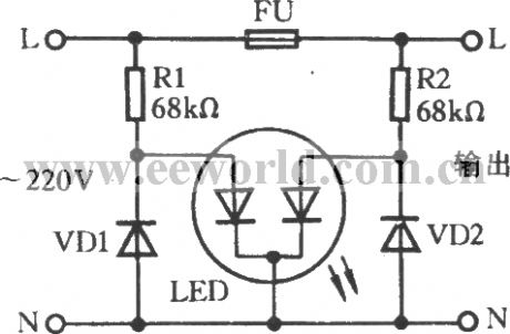
As shown in the figure, it is the fuse indicator circuit for single-phase AC circuit. LED is a discoloring light-emitting diode in the figure. When fuse FU is normal, the two light-emitting diodes in LED emit orange light; Once the fuse inside of the fuse is blown, the right light-emitting diode doesn't emit light without power, only the left one still emit red light.
(View)
View full Circuit Diagram | Comments | Reading(1975)
Automatically motor start circuit with RD9481 Doppler effect sensor
Published:2012/9/16 22:56:00 Author:Ecco | Keyword: Automatically motor start , Doppler effect sensor
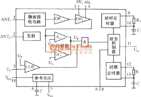
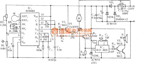
The circuit is shown as the figure. It includes the Doppler effect sensor control circuit, thyristor control circuit, music sound circuit, amplifier circuit and AC buck rectifier circuit. Doppler effect sensor integrated circuit RD9481 is the core device of the circuit, and its internal functional block diagram is shown in the following figure.
(View)
View full Circuit Diagram | Comments | Reading(2175)
Thermostatical electric radiator circuit using TC621
Published:2012/9/14 2:59:00 Author:Ecco | Keyword: Thermostatical, electric radiator
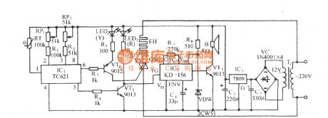
As shown in the circuit, the circuit consists of temperature control switch circuit, SCR trigger control heating circuit, music sound circuit and AC buck rectifier circuit. The circuit has wide temperature control range, simple line, good temperature control, and it does not have mechanical contacts, so it is safe, reliable, easy to set upper and lower limits of temperature. It can be widely used in the family bathroom, livestock, poultry sterile raising room and other occasions.
(View)
View full Circuit Diagram | Comments | Reading(1540)
Tubes Tauro VAA 70 power amplifier circuit diagram
Published:2012/9/13 22:18:00 Author:Ecco | Keyword: Tubes Tauro , power amplifier

Tubes Tauro VAA 70 amp's primary of output transformer has two sets of taps which can be configured in two configurations: the first is the triode connection with high fidelity, stable performance, and its output power is 30W; the second is the ultra - linear connection with high working efficiency, the output power is 60W.
(View)
View full Circuit Diagram | Comments | Reading(1238)
Simple Colpitts Oscillator circuit
Published:2012/9/16 21:58:00 Author:Ecco | Keyword: Simple, Colpitts Oscillator
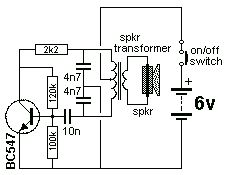
The Colpitts Oscillator is characterised by tapping the mid-point of the capacitive side of the oscillator section. The inductor can be the primary side of a speaker transformer. The feedback comes via the inductor. (View)
View full Circuit Diagram | Comments | Reading(1967)
Astable Multivibrator with 2 Transistors
Published:2012/9/16 21:57:00 Author:Ecco | Keyword: Astable Multivibrator , 2 Transistors
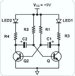
This circuit is basically simple and easy to build, it uses two transistors as active components and a few passive components like resistors, capacitors and two LEDs. The circuit makes use of the MPS2222 transistor. You can use any NPN type transistor as the basis of your circuit provided that, the transistors Emitter-Base Voltage is less than 12V and has a maximum value of 5V. (View)
View full Circuit Diagram | Comments | Reading(3834)
0 to 9 asynchronous decade counter 7490 display
Published:2012/9/16 21:56:00 Author:Ecco | Keyword: 0 to 9 , asynchronous decade counter , display
The circuit is based on asynchronous decade counter 7490(IC2), a 7 segment display (D1), and a seven segment decoder/driver IC 7446 (IC1).The seven segment display consists of 7 LEDs labelled a through g. By forward biasing different LEDs, we can display the digits 0 through 9. (View)
View full Circuit Diagram | Comments | Reading(783)
Ed Gray Motor Generator
Published:2012/9/16 21:56:00 Author:Ecco | Keyword: Ed Gray, Motor Generator

This type of design can produce a very high amperage current for a faction a second that can used to do some useful work if properly harnessed. The switching device could be a rotating spark gap as used by Nikola Tesla or some high speed electronic device, it is my belief that only glass tubes such as diodes or triode valves are really good at this and not transistors as they cannot handle the high voltage and high current produced in these devices without burning themselves out. (View)
View full Circuit Diagram | Comments | Reading(3193)
Testatika Free energy
Published:2012/9/16 21:55:00 Author:Ecco | Keyword: Testatika, Free energy

The Testatika design based on the Pidgeon/Wimshurst machine is of course only one type of electrostatic generator to build this system around. Since the early 1900s such power generators have come a long way in sophistication - and in power output - recently developed machines output 300,000 volts which can then be transformed and utilized. (View)
View full Circuit Diagram | Comments | Reading(4260)
ENERGY RECYCLING CIRCUIT
Published:2012/9/16 21:54:00 Author:Ecco | Keyword: ENERGY RECYCLING
so what happens when you flip a switch? When you try to stop the flow of current in 'zero' time its equivalent to trying to stop a freight train instantaneously. you get a huge voltage buildup dv/dt = X/0=infinity This is one example of the use of a relativistic property of electricity. We may not be able to stop freighttrains instantaneously, but we can come close with electron trains. (View)
View full Circuit Diagram | Comments | Reading(706)
Pulse-Charging Battery circuits
Published:2012/9/16 21:54:00 Author:Ecco | Keyword: Pulse-Charging Battery

With this system, the rotor is started spinning by hand. As a magnet passes the triple-wound tri-filar coil, it induces a voltage in all three coil windings. The magnet on the rotor is effectively contributing energy to the circuit as it passes the coil. One winding feeds a current to the base of the transistor via the resistor R. This switches the transistor hard on, driving a strong current pulse from the battery through the second coil winding, creating a North pole at the top of the coil, boosting the rotor on its way. As only a changing magnetic field generate a voltage in a coil winding, the steady transistor current through coil two is unable to sustain the transistor base current through coil one and the transistor switches off again. (View)
View full Circuit Diagram | Comments | Reading(3231)
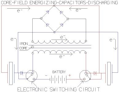
Free Energy Schematic
Published:2012/9/16 21:53:00 Author:Ecco | Keyword: Free Energy

The basic concept as I understand it, is a high frequency high voltage low current rectified and then used to charge a bank of high value capacitors and then to discharge them in pulse mode for brief period of time, nano seconds in fact by, means of a high speed electronic switching circuit or mechanical device and a rectification method that will only allow the high voltage charge to flow in one direction. (View)
View full Circuit Diagram | Comments | Reading(3050)
| Pages:331/2234 At 20321322323324325326327328329330331332333334335336337338339340Under 20 |
Circuit Categories
power supply circuit
Amplifier Circuit
Basic Circuit
LED and Light Circuit
Sensor Circuit
Signal Processing
Electrical Equipment Circuit
Control Circuit
Remote Control Circuit
A/D-D/A Converter Circuit
Audio Circuit
Measuring and Test Circuit
Communication Circuit
Computer-Related Circuit
555 Circuit
Automotive Circuit
Repairing Circuit