
Circuit Diagram
Index 325
Timer with alarm circuit
Published:2012/9/20 20:52:00 Author:Ecco | Keyword: Timer , alarm

This simple alarm timer circuit is made with 4060 which has an integrated oscillator with a good stability with a relatively wide frequency range. In the circuit diagram the oscillator frequency is set by the RC network that is connected at pins 9, 10 and 11.When the timer with alarm circuit is connected with S1, the pulse from R4 and C2 common point will reset the counter and will start the counting. When it reaches 14 bit, the 13 pin passes in state H and the auto oscillating buzzer is powered by the control transistor T1.
The time interval is adjusted with P1. In order to get intervals ranging from one minute to two hours we should do a proper sizing of the oscillator components:
1 to 30 minutes: C1=220nF; P1=500KΩ
1 to 60 minutes: C1=470nf; P1=500KΩ
1 to 120 minutes: C1=470nF; P1=1MΩ
The power supply of the timer alarm is from a 9V battery. D1 led does not does not affect the operation of the circuit and was included only to show that it works. So, R3 and D1 are optional components.
S1 can be a tilt-sensitive switch with mercury if that will be used as a kitchen clock. With the buzzer on the power consumption of the timer alarm will be around 10 mA.
Timer Alarm circuit diagram
Components valuesP1 = 500kΩ (* read the list above)R1 = 2.2MΩR2 = 18kΩR3 = R5 = 1kΩR4 = 1MΩC1 = 220nF (* read the list above)C2 = 10nFT1 = BC547IC1 = 4060?
4 Responses to “Timer with alarm circuit”
Source: electroschematics.com
(View)
View full Circuit Diagram | Comments | Reading(1440)
Emergency Lamp Battery Protector
Published:2012/9/20 20:51:00 Author:Ecco | Keyword: Emergency Lamp, Battery Protector
Emergency lamps do not have a facility to prevent the deep discharge of battery if the lamp remains on during day time. The fluorescent lamp filament also damages if it is glowing in low battery voltage. This causes blackening of the filament side that indicates the damaged filament. So we have to switch off the lamp in the morning and switch it on again in the evening. By adding this circuit in the emergency lamp you can reduce the job of daily switching. This circuit offers two advantages1. It prevents unnecessary discharge of battery during daytime2. It charges the battery only during night. This saves energy and prevents overcharging of the battery.The circuit is a Light controlled switch that connects the Emergency lamp circuit board with the power supply only during night through a relay. To keep the relay off during daytime, an LDR and a Schmitt trigger circuit are used. Light Dependent Resistor offers very high resistance around 10 Meg ohms in dark but in light it has only 100 ohms or less resistance. So it is an ideal component to switch on circuits based on the presence or absence of sun light. Here it is used to trigger the timer IC 555 which is designed as a Schmitt trigger.
Schmitt Trigger
The popular Timer IC 555 has two internal comparators. These are Threshold comparator and Trigger comparator. The Set and Reset action of these comparators can be used for On/ Off actions. Here the IC 555 functions as a Bistable with Schmitt trigger action. The upper comparator (Threshold comparator) of IC 555 trips at 2/3 of the supply voltage and the lower comparator (Trigger comparator) trips at 1/3 of the supply voltage. In the circuit, the inputs (pin6 and pin2) of both the comparators are shorted and connected to the junction of LDR and the Preset VR.
Emergency Lamp Battery Protector Circuit
In day light, LDR passes more current and the current into the upper comparator (pin6) is above 2/3 Vcc. This resets the internal Flip-Flop of IC. At the same time, the current into the lower comparator (pin2) is more than 1/3 Vcc. Both these condition causes low output from IC1. This low output keeps T1 off and the relay also remains off. Battery power supply to the emergency lamp circuit is connected through the Common and NO (Normally Open) contacts of the relay. So during daytime the emergency lamp circuits do not get power. The charging process is also prevented since the connection between the emergency lamp circuit and the battery is broken.
During night, LDR cease to conduct and the Schmitt trigger changes its state and output of IC1 becomes high. This triggers T1 as indicated by the LED. Relay then energizes and the NO contact makes connection with the Common contact of the relay. This connects the battery with the emergency lamp circuit.
Assemble the circuit on a Perf board and fix it inside the emergency lamp. Power to the circuit is obtained from the emergency lamp battery. Cut the positive supply wire of the emergency lamp circuit that goes to the battery. Solder the cut ends to the common and NO contacts of the relay. Adjust VR till Relay energize at a particular light level in the evening. Keep LDR on the back side of the lamp to prevent light falling on it.
Source: electroschematics.com (View)
View full Circuit Diagram | Comments | Reading(893)
Operational amplifier offset adjustment method
Published:2012/9/20 1:13:00 Author:Ecco | Keyword: Operational amplifier, offset, adjustment method
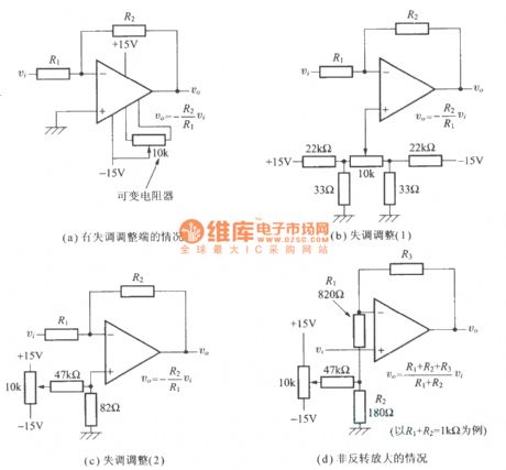
Figure a shows the adjustment when the circuit has offset.
Figure b shows the offset adjustment 1.
Figurec shows the offset adjustment 2.
Figure d shows the non inversion enlarged cases.
(View)
View full Circuit Diagram | Comments | Reading(975)
Output power amplifier circuit of operational amplifier
Published:2012/9/20 1:08:00 Author:Ecco | Keyword: Output power amplifier, operational amplifier

The circuit shown in Fig uses two transistors as an emitter follower, and diode for reducing the control dead zone (transistor base - emitter voltage UBEs = 0.7V ), and about 1mA current on the base resistor to form a bias and decide electrode quiescent current. The circuit shown in Figure b is connected to two resistors in the op-amp power connection. The quiescent current from two resistors flowing through the operational amplifier to produce about 0.7V voltage drop.
(View)
View full Circuit Diagram | Comments | Reading(1207)
The modulator circuit for indicating low- voltage high - frequency signal
Published:2012/9/20 0:53:00 Author:Ecco | Keyword: modulator , indicating , low- voltage, high - frequency, signal
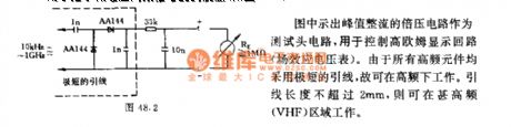
The peak rectified voltage doubler circuit shown in figure is used as a test head circuit for controlling the high ohmic display circuit (FET voltmeter). Because all high frequency components are very short leads, it can work at a high frequency. Lead length is not more than 2mm, and it may work in the high - frequency (VHF) region.
(View)
View full Circuit Diagram | Comments | Reading(592)
The broadband amplifier circuit with 600v/us conversion speed
Published:2012/9/20 0:47:00 Author:Ecco | Keyword: broadband amplifier , 600v/us, conversion speed

The circuits shown in Figures a and b have different signs of the input signal and input impedance Ze, and the main technical data is shown in the following table.
(View)
View full Circuit Diagram | Comments | Reading(974)
Wideband op amp circuit
Published:2012/9/19 22:51:00 Author:Ecco | Keyword: Wideband op amp

The circuit shown in Figure has overload protection measures. When the circuit has DC-coupled input, the input terminal can be connected to RC blocking network. When the switch S is opened, voltage amplification factor Ku = 1 ( voltage follower ). When S is closed, Ku = 10. For example, R1 = 100kΩ, R2 = R1 / ( Ku- 1 ) = 100/ 9 = 11.1kΩ. R2 = 10kΩ, the circuit is connected to a 2.5kΩ potentiometer Rp in series. The circuit shown as Figure b uses 10 ~ 20V voltage source, this input terminal is connected to a voltage divider.
(View)
View full Circuit Diagram | Comments | Reading(1017)
Active filter circuit with variable states
Published:2012/9/19 22:38:00 Author:Ecco | Keyword: Active filter , variable states

The circuit shown in figure has 2 outputs UA1 and UA2, the former is a high -pass filter output, and the latter is a band-pass filter output. The operational amplifiers A1 , A2 , A3 and A4 can use quad op amp OP-11FY or a LM124. Capacitor should use polystyrene film capacitor, and its accuracy should be less than ± 10%.
(View)
View full Circuit Diagram | Comments | Reading(1073)
High pass filter ( differentiator ) circuit
Published:2012/9/19 22:27:00 Author:Ecco | Keyword: High pass filter, differentiator

The circuit is the high-pass filter which is also used as pulse differentiator, output voltage is Ua and input voltage is Ue. Output voltage variation is about 12dB / octave. The value of the resistor R3 and R2 is equal.
(View)
View full Circuit Diagram | Comments | Reading(1048)
DC shunt motor commutation circuit
Published:2012/9/19 3:40:00 Author:Ecco | Keyword: DC shunt motor , commutation
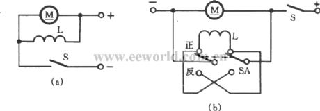
DC shunt motor's excitation coil and armature are connected in parallel, and it is shown in figure (a). If both the positive and negative poles are switching, it is impossible to change the direction of rotation of the motor. Therefore, it is the same with separately excited motor, you can change the direction of rotation by simply changing the armature or field coil wiring. Figure (b) shows a circuit which realize motor commutation by changing the exciting coil terminals.
(View)
View full Circuit Diagram | Comments | Reading(1075)
Motor winding heating and drying circuit with welding transformer
Published:2012/9/19 3:34:00 Author:Ecco | Keyword: Motor winding, heating , drying , welding transformer

For three - phase motor, the heating single phase power supply should be controlled about 110V, it can use a welding transformer to reduce the power supply voltage to 380V or 220V and access to the three-phase stator windings connected in series, and the circuit is shown in Fig. A stator winding current ( measured by the ammeter A ) is 70 % to 80% of the rated motor current, when it is energized 7 to 8 hours, the motor will be dried.
(View)
View full Circuit Diagram | Comments | Reading(2603)
The armature ground fault test circuit using traffic lights
Published:2012/9/19 2:35:00 Author:Ecco | Keyword: armature ground fault, test circuit , traffic lights
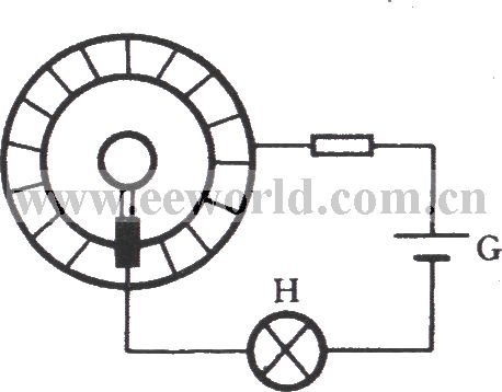
The armature is an important part of tributary electric motor and single-phase series motor, and its common faults include winding grounding, short circuit and reversed connection. These can be detected with a multimeter and megger. As shown in figure, it is a test schematic diagram with traffic light. When it is measured, the black stick of light is connected to the shaft ( ground ), red bar table is touched commutator segment. If the lamp H is not bright, it means that there is not a pathway between winding or commutator and shaft, no ground fault. If the light bulb is lit, it has existed ground fault and should be promptly repaired.
(View)
View full Circuit Diagram | Comments | Reading(1677)
Voice control music outlet circuit 1 using NJM2072D
Published:2012/9/19 2:26:00 Author:Ecco | Keyword: Voice control , music outlet


As shown in the figure, the circuit consists of acoustic sensor, voice integrated circuit, relay control circuit, songs sound circuit and AC buck rectifier circuit and other components, it can be used for the voice automatic lights, voice control musical fountain, voice barricades indicator and voice-activated automatic doors. ICl uses voice ASIC NJM2072D, it is the core of the circuit devices, and its functional block diagram is shown in the following figure.
(View)
View full Circuit Diagram | Comments | Reading(1755)
Acousto-optic control lantern with music sound circuit using SH805
Published:2012/9/19 2:18:00 Author:Ecco | Keyword: Acousto-optic control lantern , music sound circuit

As shown in the figure, the circuit consists of voice switch, light control switch, monostable timing circuit lantern control circuit and music sound circuit. The lamp control circuit has 16 functions of program which can automatically transform colorful light, and its control method is sound and light double control, and it won't be lit during the day, and lit at night. When the the lantern flashes, it is also accompanied by the melodious waltz music.
(View)
View full Circuit Diagram | Comments | Reading(718)
The barn ventilation cooling device circuit using TC626
Published:2012/9/19 2:02:00 Author:Ecco | Keyword: barn , ventilation, cooling device

As shown in Figure, the circuit consists of thermostat switch, thyristor control circuit, analog utterance circuit and AC buck rectifier circuit and other components. When the ambient temperature exceeds the set temperature, the circuit can be automatically ventilate and cooling with 3 sound animal sounds.
(View)
View full Circuit Diagram | Comments | Reading(964)
Proximity switch circuit with TCA205A
Published:2012/9/19 1:58:00 Author:Ecco | Keyword: Proximity switch
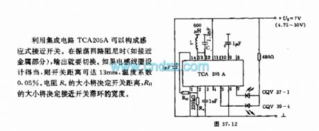
It uses integrated circuit TCA205A to form an inductive proximity switch. If the inductance coil is properly designed, the switching distance can be up to 13mm, the temperature coefficient is 0.05 % . The size of the resistor Ra will determine the switching distance, the RH will determine the width of the switch hysteresis loops.
(View)
View full Circuit Diagram | Comments | Reading(1955)
Gree programmed box fan circuit
Published:2012/9/19 1:40:00 Author:Ecco | Keyword: Gree, programmed , box fan

Gree programmed box fan circuit uses monolithic Manifold RTS501-1B and peripheral circuits, and it has a weak, medium, strong wind speeds; ordinary wind, natural wind and sleep wind. It can choose any 9 wind patterns by the combination of wind speed and wind patterns key. The 7.5-hour timing control is set by 0.5 hoursunit accumulating. It is set key beep and self- diagnostic input situation, and each function is corresponding to the light-emitting diode display. The circuit is shown as the figure.
(View)
View full Circuit Diagram | Comments | Reading(1344)
The terminal and internal function of operational amplifier
Published:2012/9/20 1:14:00 Author:Ecco | Keyword: terminal , internal function , operational amplifier

Figure a shows the signs and terminals.
Figure b shows the internal structure of operational amplifier.
(View)
View full Circuit Diagram | Comments | Reading(694)
The precious flower greenhouse thermostat control circuit with birdsong sound
Published:2012/9/19 3:36:00 Author:Ecco | Keyword: precious flower, greenhouse , thermostat control , birdsong sound

The circuit is shown as the figure. It consists of a temperature sensor, temperature control circuit, relay control heating circuit, birdsong sound circuit and AC buck rectifier circuit and other components. It enables flowers glasshouse to maintain the set temperature; when it is heating, it can also issue several crisp birdsong.
(View)
View full Circuit Diagram | Comments | Reading(1515)
The magnetic circuit trip - voltage converter circuit with magnetic components
Published:2012/9/19 2:13:00 Author:Ecco | Keyword: magnetic circuit, trip - voltage converter , magnetic components
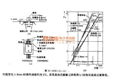
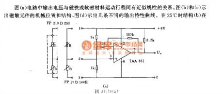
As shown in Figure a, it has a approximately linear relationship between the output voltage and the movement of the magnet or soft magnetic materials. Figures b and c illustrate the mechanical position and structure of the magneto-sensitive element, Figure d shows several different output characteristic curves. When temperature is at 25 ℃, the structure b changes 0.8mm, linearity error is about 5%. It uses differential magnetic components shown as Figure c to reduce structural error.
(View)
View full Circuit Diagram | Comments | Reading(630)
| Pages:325/2234 At 20321322323324325326327328329330331332333334335336337338339340Under 20 |
Circuit Categories
power supply circuit
Amplifier Circuit
Basic Circuit
LED and Light Circuit
Sensor Circuit
Signal Processing
Electrical Equipment Circuit
Control Circuit
Remote Control Circuit
A/D-D/A Converter Circuit
Audio Circuit
Measuring and Test Circuit
Communication Circuit
Computer-Related Circuit
555 Circuit
Automotive Circuit
Repairing Circuit