
Circuit Diagram
Index 338
Digital Voice Recorder/Playback (UM5100)
Published:2012/9/12 20:56:00 Author:Ecco | Keyword: Digital , Voice Recorder, Playback
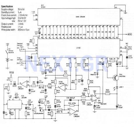
This Circuit is based on the UM5100 which can record speech into a digital memory and then play it back. The device is designed to be used directly with static RAM's up to 256K bits, or with EPROM 's or ROM's for playback only. High quality voice reproduction is possible and note that it is not a computer voice , it is the original speaker's voice played back. The bit rate is adjustable from 10kbs to 28kbs with higher quality at faster bit rates.
Source: NEXT.GR (View)
View full Circuit Diagram | Comments | Reading(2706)
Speech Pitch Controller (MSM6322GSK)
Published:2012/9/12 20:56:00 Author:Ecco | Keyword: Speech Pitch, Controller

That circuit uses the MSM6322GSK which is only available in small 24 pin plastic SOP style package. A speech pitch converter IC that operates in real time and requires very few external components. It has a microphone preamplifier and line level input and the output requires only a single transistor to directly drive a loudspeaker. As well as the microphone preamplifier, the IC contains a 4th order low pass filter on input and a 3rd order low pass filter on output. In addition there is a build-in 8-bit A/D converter and 9-bit D/A converter.
Source: NEXT.GR (View)
View full Circuit Diagram | Comments | Reading(798)
AM reciever with TDA1072A
Published:2012/9/12 20:55:00 Author:Ecco | Keyword: AM reciever
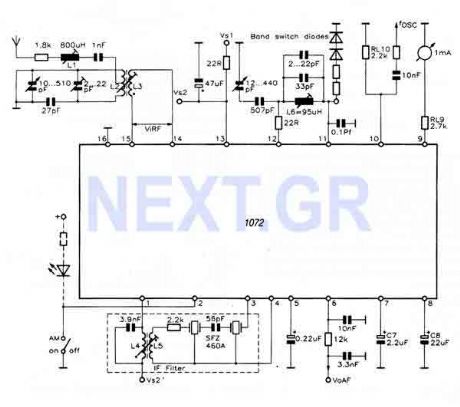
This reciever uses the TDA1072A which is a complete AM reciever on a chip and it only requires comparitively few peripheral components to complete a high quality AM radio Circuit. Unlike some other AM radio ICs, a minimum number of external tuned inductors are used to preserve reasonable performance, selectivity and quality of output. Only two of these, an RF input transformer and a single winding oscillator coil need be tuned either capacitively or inductively.
Source: NEXT.GR (View)
View full Circuit Diagram | Comments | Reading(1987)
40 Watt Audio power Amplifier LM3876
Published:2012/9/12 20:55:00 Author:Ecco | Keyword: 40 Watt, Audio power Amplifier

This Circuit is based on the LM3876. A 11-pin plastic package IC with high performance audio power amplifier, an output mute function which can be used to eliminate switch-on and switch-off thumps to the loudspeaker load. It is capable of delivering 40W continuously into 8ohm load, and is fully protected using established techniques. The output stage is protected against short circuit to ground or either supply rail. Protection against transients from inductive loads is also provided at the output stage via internal clamp diodes.
Source: NEXT.GR (View)
View full Circuit Diagram | Comments | Reading(2421)
40 Watt Hi-Fi amplifier (TDA1514AN-7)
Published:2012/9/12 20:54:00 Author:Ecco | Keyword: 40 Watt, Hi-Fi amplifier

This very high quality audio amp is based on the TDA1514A, a 9-pin flat package IC. The heatsink must be insulated from ground. The amplifier will deliver 40 watt into an 8ohm load with a 27.5 volt power rail or 40 watt into 4ohm load with a 21 volt power rail. The IC is designed to meet the requirements of digital sound sources such compact disk players etc. The total harmonic distortion at 32watt is less than 0.0032%.
Source: NEXT.GR (View)
View full Circuit Diagram | Comments | Reading(1203)
TDA2050V HiFi amplifier
Published:2012/9/12 20:53:00 Author:Ecco | Keyword: HiFi amplifier

This circuit uses a high quality audio amplifier IC in a 5-pin TO220 package that does not require insulating washers between the metal tab and heatsink in single rail supply applications. The amp can provide 32 watt rms into 4ohm load and 25 watt rms into 8ohm. (View)
View full Circuit Diagram | Comments | Reading(1109)
Simple Coil-less AM receiver
Published:2012/9/12 20:52:00 Author:Ecco | Keyword: Simple , Coil-less , AM receiver
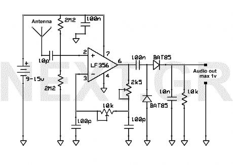
This AM receiver is working perfectly without the need of coils or even a variable capacitor. The LF356 is the basic component. P1 and P2 are the frequency selectors. Use a small telescopic antenna. The stations selectivity is not perfect but is acceptable. (View)
View full Circuit Diagram | Comments | Reading(2410)
Quality FM-TV micro transmitter 40-200 Mhz
Published:2012/9/12 20:52:00 Author:Ecco | Keyword: Quality, FM-TV, micro transmitter, 40-200 Mhz

This Transmitter can be powered by a battery 9V (not more than 12V). You can connect your music source where the microphone is or use a simple condenser microphone. The range of signal can reach 400 meters in open air. The wide range of frequency is up to you. Tune it at FM band (88-108) or TV band 40-80Mhz. Play with the Coil and the variable capacitor to tune it to any frequency you want as long as you got the receiver. (View)
View full Circuit Diagram | Comments | Reading(2652)
Room Ioniser circuit
Published:2012/9/12 20:51:00 Author:Ecco | Keyword: Room Ioniser
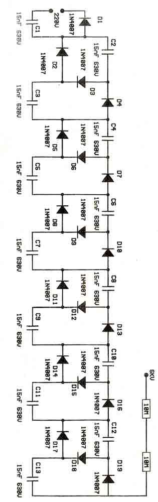
This is a voltage multiplier circuit acting as an Ioniser. Its calculated to feed 220V from mains and the output is about 6KV. Caution should take with the circuit as can be dangerous due to mains. You can place a needle at the output 3cm long. (View)
View full Circuit Diagram | Comments | Reading(1993)
Anti-RF filtered power supply 12-14 Volt / 3A
Published:2012/9/12 20:50:00 Author:Ecco | Keyword: Anti-RF , filtered , power supply, 12-14 Volt / 3A

This power supply is dedicated for use with rf equipments like, linear amplifiers, transmitters, receivers, and in every application that clean an-noisy signal is required. The circuit is very simple and you can drive it with a 220V/18V/3A transformer at the pins 1and 2. (View)
View full Circuit Diagram | Comments | Reading(971)
TV signal amplifier 470Mhz-860Mhz
Published:2012/9/12 20:49:00 Author:Ecco | Keyword: TV , signal amplifier, 470Mhz-860Mhz

This amplifier can amplify to 10dB the RF signal from antenna working as class A and is based on transistor BFQ34 of Philips. The transistor comes in case SOT122A. You may find the BFQ34T in market but better do not use it as it has different characteristics. (View)
View full Circuit Diagram | Comments | Reading(1479)
Simple light-switch circuit
Published:2012/9/12 20:49:00 Author:Ecco | Keyword: Simple light-switch

The circuit is a light switch who triggers when light drops on photo resistor. It is fairly simple in construction and can be used in a million applications. The photoresistor and the trimmer work as a voltage divider and also polarize the transistor TR1. TR1 triggers TR2 and TR2 drives the relay. Trimmer R7 is for adjusting the sensitivity of the circuit. (View)
View full Circuit Diagram | Comments | Reading(738)
HI-FI Audio Amplifier 60W
Published:2012/9/12 20:48:00 Author:Ecco | Keyword: HI-FI Audio Amplifier, 60W

This amplifier has a high quality circuit that includes full sort circuit protection and very low T.H.D. at full range of frequency. It needs simmetrical power supply +-40V. The power transistors at the output are connected as DARLINGTON and both needs heatsinks. The power can reach 60 watts at 8 ohms or 80 Watts at 4 ohms. (View)
View full Circuit Diagram | Comments | Reading(3127)
High Voltage Power Supply 10kV
Published:2012/9/12 20:47:00 Author:Ecco | Keyword: High Voltage , Power Supply , 10kV

Be very carefull with this power supply because uses 220V mains and has 10KV at output. (View)
View full Circuit Diagram | Comments | Reading(1417)
Short wave radio for PC
Published:2012/9/12 20:47:00 Author:Ecco | Keyword: Short wave radio, PC

This Cheap circuit will amaze you with its wide range recieving signal between 6 and 17Mhz (49-19meters). Power supply is not necesery, just connect it to your pc, place the antena to your home piping network and voila! (View)
View full Circuit Diagram | Comments | Reading(5525)
PC audio amplifier 12Watt
Published:2012/9/12 20:45:00 Author:Ecco | Keyword: PC, audio amplifier, 12Watt

The circuit uses the TDA2030 which is a monolithic integrated circuit in Pentawatt? package, intended for use as a low frequency class AB amplifier. Typically it provides 14W output power (d = 0.5%) at 14V/4??; at ± 14V or 28V, the guaranteed output power is 12W on a 4?? load and 8W on a 8?? (DIN45500). The TDA2030 provides high output current and has very low harmonic and cross-over distortion. (View)
View full Circuit Diagram | Comments | Reading(1944)
10Watt HI-FI Amplifier (TDA2002)
Published:2012/9/12 20:44:00 Author:Ecco | Keyword: 10Watt, HI-FI Amplifier

A very small but good quality amplifier circuit that is also fairly cheap. It is based on TDA2002 which offers very low distrortion. Power should be 12-15 volt 1,2A. The amplifier frequency responce ranges from 40Hz to 15Khz. A good heatsink is required. At the input you can connect your mp3 player or your pc audio out etc. (View)
View full Circuit Diagram | Comments | Reading(5902)
Ni-Cd Baterry Charger 12-18V
Published:2012/9/12 20:44:00 Author:Ecco | Keyword: Ni-Cd , Baterry Charger, 12-18V

A clever charger circuit that safely can charge any Ni-Cd battery. Offers charge current sellection, polarization detection and protection and the ability to connect many batterys in siries. Ni-Cd bateries can be recharged more than 1000 times before become useless. the charging current shoud be the 1/10 of the (Ah) of the battery. The bateries need 14 hours to be fully charged. (View)
View full Circuit Diagram | Comments | Reading(3649)
AM-FM-TV RF AMPLIFIER
Published:2012/9/12 20:44:00 Author:Ecco | Keyword: AM-FM-TV, RF AMPLIFIER

The circuit is a universal amplifier that can amplify any rf signal. You can use the BF194 or the BF198. Make sure you use coaxial cable. (View)
View full Circuit Diagram | Comments | Reading(3991)
0-60sec start-stop timer with 555
Published:2012/9/12 20:43:00 Author:Ecco | Keyword: 0-60sec, start-stop timer , 555

This timer is ideal for small aplications. Due to its simple structure, its usage and nevertheless its universal character, this mini timer is usable in the most current applications needing time intervals, from some seconds through approximately 60 minutes. By simple modifications it is possible to adjust the maximum time and the timing scale, as necessary. A strong output, made by a relay, permits to adapt, on the input and the output, whatever apparatus. (View)
View full Circuit Diagram | Comments | Reading(3818)
| Pages:338/2234 At 20321322323324325326327328329330331332333334335336337338339340Under 20 |
Circuit Categories
power supply circuit
Amplifier Circuit
Basic Circuit
LED and Light Circuit
Sensor Circuit
Signal Processing
Electrical Equipment Circuit
Control Circuit
Remote Control Circuit
A/D-D/A Converter Circuit
Audio Circuit
Measuring and Test Circuit
Communication Circuit
Computer-Related Circuit
555 Circuit
Automotive Circuit
Repairing Circuit