
Circuit Diagram
Index 336
Active Antenna for 10 to 30 MHz
Published:2012/9/13 20:37:00 Author:Ecco | Keyword: Active Antenna , 10 to 30 MHz
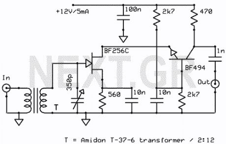
The schematic shown, is a 2 transistor signal amplifier between 10 MHz to 30 MHz. The BF256C and the BF494 are very popular transistors and are easy to find. The transformer works as insulator and amplifier.
Source: NEXT.GR (View)
View full Circuit Diagram | Comments | Reading(2210)
0-30 Volts / 2,5A Variable Power Supply
Published:2012/9/13 20:37:00 Author:Ecco | Keyword: 0-30 Volts / 2,5A , Variable Power Supply

This is a high quality power supply with a continuously variable stabilized output adjustable between 0 and 30VDC. the LM 723 is the heart of the power supply which drives the BD137 and then the 2N3055. The circuit provides short circuit protection. And has great stability at voltage changes.
Source: NEXT.GR (View)
View full Circuit Diagram | Comments | Reading(2690)
Simple Infra-Red Transmitter/reciever Shematics
Published:2012/9/13 3:53:00 Author:Ecco | Keyword: Simple , Infra-Red Transmitter, reciever

This 1 channel infrared transmitter/receiver remote control is the cheapest and simplest you can find. The transmitter transmits a sequence of pulses on 36 KHz frequency carrier. The diodes are Schottky type because of their low voltage drop (only 0.2V). The ripple counter 74HC4060 contains an oscillator which controls the frequency carrier to be 36KHz.
Source: NEXT.GR (View)
View full Circuit Diagram | Comments | Reading(2225)
Active Antenna Circuit for 10KHz to 100MHz
Published:2012/9/13 3:52:00 Author:Ecco | Keyword: Active Antenna , 10KHz to 100MHz

This active antenna schematic can be used to frequency range from 10 KHz to 100 MHz. The length of the Antenna can be between 0.5 to 1 meter long. The power consumption is 20-30mA.
Source: NEXT.GR (View)
View full Circuit Diagram | Comments | Reading(2985)
Free energy collector circuit
Published:2012/9/13 3:52:00 Author:Ecco | Keyword: Free energy collector

This circuit converts surrounding radio frequency waves to electric power. It can provide 40 Volts at 10 Watts indefinitely. The output power can be improved playing with the antenna. Placing the antenna near large metal objects gives more power. Antenna should be more than 150 feet long wire, placed horizontally as high as you can for best results. The pointing direction also is critical to the output. Keep the circuit as close to antenna as posible. You can also experiment with dishes etc. The circuit also acts as a passive detector. When large metal objects passes the power gets higher. Also its sensitivity can detect energy changes on earth and so it can used as early warning of seismic activity.
Source: NEXT.GR (View)
View full Circuit Diagram | Comments | Reading(4895)
Microphone Preamplifier with SSM 2015 P
Published:2012/9/13 3:51:00 Author:Ecco | Keyword: Microphone, Preamplifier, SSM
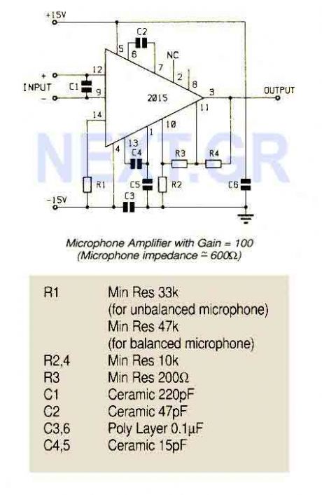
An ultra low noise audio preamplifier particularly suited to microphone preamplification including balanced microphones. The IC features wide bandwidth, low distortion only 0.007% at a gain of 100.
Source: NEXT.GR (View)
View full Circuit Diagram | Comments | Reading(1642)
Switching Regulator with L4972A
Published:2012/9/13 3:51:00 Author:Ecco | Keyword: Switching Regulator
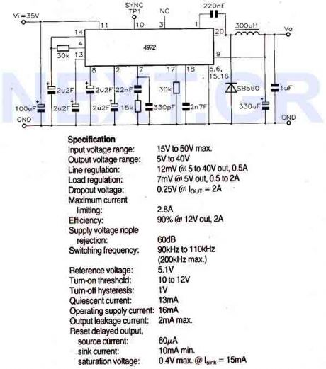
The LA9472A is a 2A monolithic step down switching regulator operating in continuous mode and realized in a new BCD technology allowing the integration of isolated, vertical DMOS power transistors with mixed CMOS/bipolar transistors. The device can deliver 2A at an output voltage adjustable from 5.1V to 40V and contains diagnostic and control functions that make it particularly suitable for microprocessor based systems.
Source: NEXT.GR (View)
View full Circuit Diagram | Comments | Reading(625)
FSK Demodulator/Tone Decoder with RC2211N
Published:2012/9/13 3:46:00 Author:Ecco | Keyword: FSK, Demodulator, Tone Decoder
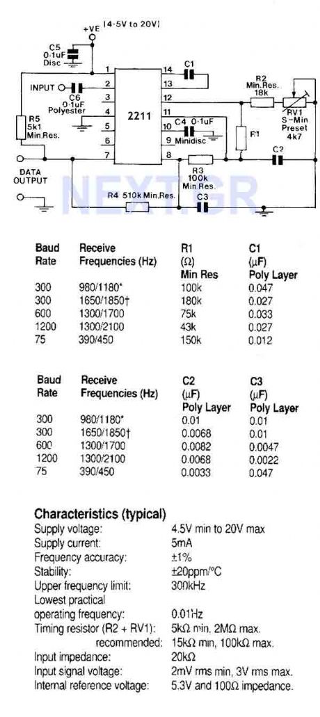
A monolithic phase locked loop for data communications. The IC contains a basic phase locked loop for tracking an input signal within the pass band, a quadrature phase detector which provided carrier detector and an FSK voltage comparator which provides FSK demodulation. In the circuit shown, the IC is used as an FSK demodulator such as would be found in the receiver circuit of a modem.
Source: NEXT.GR (View)
View full Circuit Diagram | Comments | Reading(0)
PAL Colour Encoder (TEA2000-V1)
Published:2012/9/13 3:45:00 Author:Ecco | Keyword: PAL , Colour , Encoder
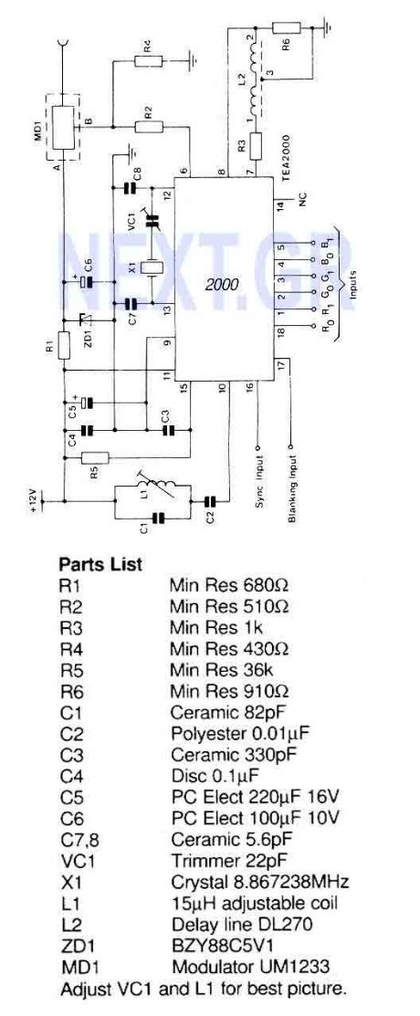
A PAL color encoder and video summer which requires just composite sync and composite blanking inputs, and a 6-bit binary coded input giving the color information. The inputs are organized as 2 bits per primary color with gamma correction automatically applied to the resultant luminance and chrominance levels.
Source: NEXT.GR (View)
View full Circuit Diagram | Comments | Reading(2102)
TV Pattern Generator (ZNA234E)
Published:2012/9/13 3:45:00 Author:Ecco | Keyword: TV Pattern, Generator
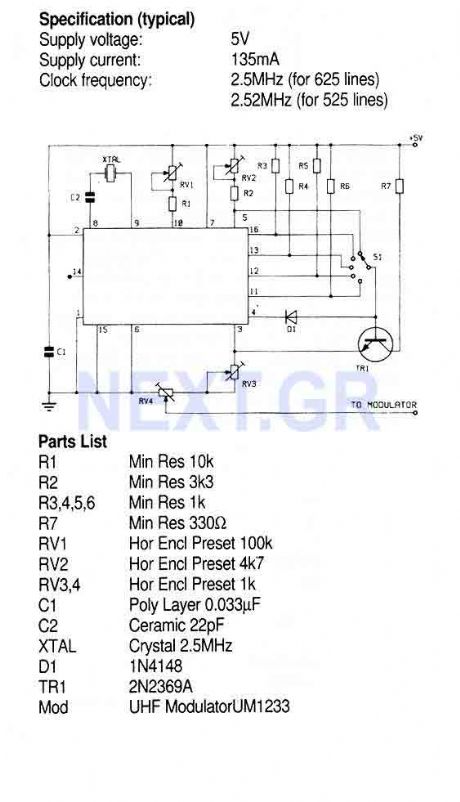
This Circuit uses the ZNA234E IC which makes available all the waveforms necessary to produce the crosshatch, dot and greyscale test patterns on a television screen. The composite video output can be injected directly into the video input of a receiver or used to drive a modulator for connection to the aerial socket.
Source: NEXT.GR (View)
View full Circuit Diagram | Comments | Reading(1952)
Astable/Monostable oscillator using 555 IC
Published:2012/9/13 3:44:00 Author:Ecco | Keyword: Astable/Monostable , oscillator , 555 IC
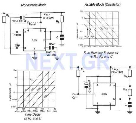
The 555 is a highly stable device for generating accurate time delays or oscillation. Aditional terminals are provided for triggering or resetting if desired. In the time delay (monostable) modeof operation the time is precisely controlled by one extrernal resistor and one capacitor. For stable operation as an oscillator, the free running frequency and the duty cycle are both accurately controlled with two external resistors and one capacitor.
Source: NEXT.GR (View)
View full Circuit Diagram | Comments | Reading(700)
Magnetic Cartridge Preamplifier (LT1028CN8)
Published:2012/9/13 3:43:00 Author:Ecco | Keyword: Magnetic Cartridge , Preamplifier
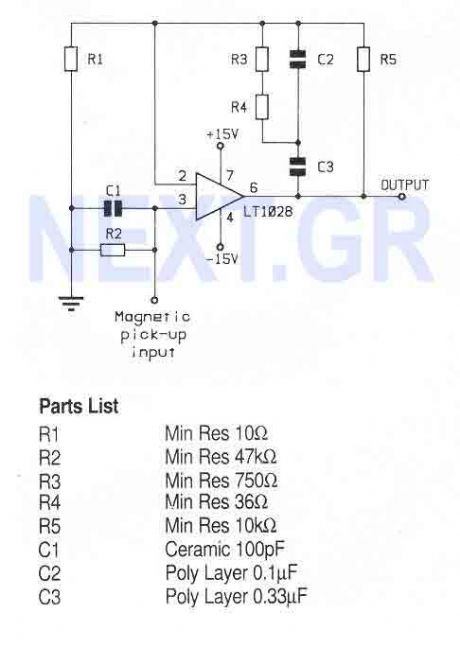
A high performance op-amp that sets a new standard of excellence in noise performance only 0.9nV/Hz with low source resistances. Total harmonic distortion is less than 0.01%. The op-amp is suitable for use in high quality audio, low noise frequency synthesizers, infrared detectors etc.
Source: NEXT.GR (View)
View full Circuit Diagram | Comments | Reading(1053)
Capacitor buck driving LED circuit 3
Published:2012/9/13 1:56:00 Author:Ecco | Keyword: Capacitor buck , driving , LED

The circuit usestwo anti-parallel LEDs to rectify AC buck voltage, and itcan be widely used in night light, button indicatorlight, position indicator and other occasions.
(View)
View full Circuit Diagram | Comments | Reading(2178)
Active double secondary band-pass filter circuit
Published:2012/9/13 1:40:00 Author:Ecco | Keyword: Active double, secondary band-pass filter

The center frequency is 1kHz, quality factor Q=50, gain KV=100( about 40dB).
(View)
View full Circuit Diagram | Comments | Reading(944)
DC series motor commutation circuit
Published:2012/9/13 1:37:00 Author:Ecco | Keyword: DC series , motor commutation

The communication method of series excitation motor is to individually change the armature current or the current direction of the excitation coil individually, then it can achieve the change of rotation direction. The circuit is shown as the figure, the figure (a) is a schematic diagram of the series excited motor, and figure (b) is a series motor commutation circuit diagram.
(View)
View full Circuit Diagram | Comments | Reading(1434)
Voice-activated automatic light accompanied music sound circuit using SK-IV
Published:2012/9/12 22:42:00 Author:Ecco | Keyword: Voice-activated, automatic light , accompanied music sound

The circuit is shown in Figure, and it includes acoustic transducer, voice control circuit, SCR control circuit, music sound circuit and AC buck rectifier circuit. BH-SK-IV is the core device of the circuit.
(View)
View full Circuit Diagram | Comments | Reading(1128)
Vice control music outlet circuit using SL517A
Published:2012/9/12 22:29:00 Author:Ecco | Keyword: Vice control, music outlet


The circuit is shown in Figure, and it is composed of acoustic sensor, voice control IC, relay control circuit, song voice circuit and AC buck rectifier circuit. Voice control IC uses SL517A which contains high-gain amplifier, bistable flip-flop and buffer output level, and it has two packages of dual in-line and black ointment. Its internal functional block diagram is shown as below.
(View)
View full Circuit Diagram | Comments | Reading(893)
Multifunction fans with birdsong control circuit using LC902
Published:2012/9/12 22:55:00 Author:Ecco | Keyword: Multifunction fans , birdsong control

The circuit is shown as the figure. The core device of fan control circuit is LC902 which is the LC901 's improved device, and compared with LC901, LC902 increases sleeping wind output and key audio output.
(View)
View full Circuit Diagram | Comments | Reading(857)
The frequency-selecting voice control music outlet circuit with LK001
Published:2012/9/12 22:51:00 Author:Ecco | Keyword: frequency-selecting , voice control , music outlet


The circuit is shown as the figure. It includes acoustic sensor BM, voice control integrated circuit, SCR control circuit, imitation sound circuit and AC buck rectifier circuit and so on . Voice control ASIC LK001 is the core component of the control circuit, its internal circuit functional block diagram is shown in the following figure.
(View)
View full Circuit Diagram | Comments | Reading(997)
Natural wind fan control circuit with cricket sounds
Published:2012/9/12 22:48:00 Author:Ecco | Keyword: Natural wind, fan control , cricket sounds


The circuit is shown as the figure. It includes multivibrator circuit, SCR control circuit, voice sound circuit, audio amplifier circuit and AC buck rectifier circuit. It enables fans to send natural wind with varying soft wind power and accompanied by autumnal cricket sounds. Time-base circuit 555 and R1 , RP1 , VD1, VD2 , C2 form a low-frequency multivibrator with adjustable duty cycle, and the oscillation frequency is:
(View)
View full Circuit Diagram | Comments | Reading(1159)
| Pages:336/2234 At 20321322323324325326327328329330331332333334335336337338339340Under 20 |
Circuit Categories
power supply circuit
Amplifier Circuit
Basic Circuit
LED and Light Circuit
Sensor Circuit
Signal Processing
Electrical Equipment Circuit
Control Circuit
Remote Control Circuit
A/D-D/A Converter Circuit
Audio Circuit
Measuring and Test Circuit
Communication Circuit
Computer-Related Circuit
555 Circuit
Automotive Circuit
Repairing Circuit